Sony XM-5150GSX Operating Instructions (primary manual) - Page 1
Sony XM-5150GSX - Stereo Power Amplifier Manual
 |
View all Sony XM-5150GSX manuals
Add to My Manuals
Save this manual to your list of manuals |
Page 1 highlights
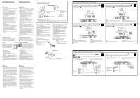
Features • Maximum power output of 80 watts × 4 + 300 watts (at 4 ohms). • Features a 2 channel-input / 5 channel-output function that makes it possible to carry a 2-way multi system even with a single line output from the car stereo. • Low-pass filter, high-pass filter circuit are builtin. • Protection circuit and indicator provided. • Pulse power supply* for stable, regulated output power. * Pulse power supply This unit has a built-in power regulator which converts the power supplied by the DC 12 V car battery into high speed pulses using a semiconductor switch. These pulses are stepped up by the built-in pulse transformer and separated into both positive and negative power supplies before being converted into direct current again. This light weight power supply system provides a highly efficient power supply with a low impedance output. Caractéristiques • Puissance de sortie maximale de 80 watts × 4 + 300 watts (à 4 ohms). • Intègre une fonction d'entrée à 2 canaux/sortie à 5 canaux compatible avec un multisystème à 2 voies même avec une sortie de ligne signal via la stéréo. • Un circuit de filtre passe-bas et de filtre passe-haut sont intégrés. • Circuit de protection fourni. • Alimentation électrique par impulsions* pour une puissance de sortie stable, régulée. * Alimentation électrique par impulsions Cet appareil est équipé d'un régulateur de puissance intégré qui convertit la puissance fournie par une batterie de voiture de 12 V CC en impulsions ultra-rapides au moyen d'un commutateur à semi-conducteur. Ces impulsions sont amplifiées par le transformateur d'impulsions intégré et séparées en alimentation positive et négative avant d'être reconverties en courant continu. Ce système d'alimentation de faible poids assure une alimentation électrique très efficace pour une sortie d'impédance faible. Location and Function of Controls Emplacement et fonction des commandes 1 POWER indicator Lights up in green during normal operation. 2 PROTECTOR indicator • OVER CURRENT: Lights up in red when input signal overload. • OFFSET: Lights up in red when the voltage going out to the Speaker terminal or the Pin Jack is too high. • THERMAL: Lights up in red when the temperature rises to an unsafe level. 3 TEST TONE button When the button is pressed, if the test tone can be heard from the connected speakers, operation is normal. 46 Cut-off frequency adjustment control Sets the cut-off frequency (50-300 Hz) for the high-pass or low-pass filters. 5 LEVEL adjustment control The input level can be adjusted with this control. Turn it toward MAX when the output level of the car audio seems low. To reduce noise, turn the LEVEL control (gain) of the amplifer to MIN and the volume of the car audio up. 7 INPUT MODE select switch When no input lead is connected to SUBWOOFER INPUT, the switch can be used to change the SUBWOOFER OUTPUT as follows. F : Outputs the signal that has been input to the FRONT input jack. F+R : Outputs the signal that has been input to the FRONT and REAR input jacks. 8 SUBWOOFER LEVEL adjustment control The input level can be adjusted with this control when using source equipment made by other manufacturers. Turn it to MAX when the output level of the car audio seems low. To reduce noise, turn the LEVEL control (gain) of the amplifer to MIN and the volume of the car audio up. POWER/PROTECTOR POWER OVER CURRENT OFFSET THERMAL 3 45 1 Indicateur POWER S'allume en vert en cours de fonctionnement normal. 2 Indicateur PROTECTOR • OVER CURRENT: S'allume en rouge lorsque le signal d'entrée est surchargé. • OFFSET: S'allume en rouge lorsque la tension de sortie vers le terminal du hautparleur ou la prise à broches est trop élevée. • THERMAL: S'allume en rouge lorsque la température atteint un niveau trop dangereux. TEST TONE FRONT 3 Touche TEST TONE Si, lorsque vous appuyez sur cette touche, vous entendez la tonalité de test depuis les enceintes raccordées, cela signifie que le fonctionnement est normal. 46 Commandes de réglage de la fréquence de coupure Règle la fréquence de coupure (50-300 Hz) pour les filtres passe-bas ou passe-haut. 50Hz 300Hz MIN MAX 5 Commande de réglage LEVEL HPF LEVEL Le niveau d'entrée peut se régler avec cette commande. Tournez vers MAX lorsque le niveau de sortie de l'xinstallation radio paraît faible. Mettez-le sur MAX lorsque le niveau de sortie de l'installation audio paraît faible. Pour réduire les parasites, tournez la commande LEVEL (gain) de l'amplificateur sur 50Hz 300Hz MIN MAX MIN et augmentez le volume sur l'autoradio. HPF LEVEL 7 Sélecteur INPUT MODE REAR Si aucun fil d'entrée n'est raccordé à SUBWOOFER INPUT, le sélecteur peut être utilisé pour changer SUBWOOFER OUTPUT comme suit. F: Sortie du signal entré via la prise d'entrée FRONT. 6 F+R: Sortie du signal entré via les prises d'entrée FRONT et REAR. 8 Commande de réglage SUBWOOFER LEVEL (NIVEAU DE l'ENCEINTE D'EXTREMES GRAVES) Le niveau d'entrée peut se régler avec cette commande lors de l'utilisation LPF d'équipements source d'autres fabricants. Mettez-le sur MAX lorsque le niveau de sortie de l'installation audio paraît faible. Pour réduire les parasites, tournez la commande LEVEL (gain) de l'amplificateur sur MIN et augmentez le volume sur l'autoradio. 50Hz 300Hz F F+R MIN MAX MODE LEVEL SUB WOOFER 78 Cut-off frequency/Fréquence de coupure dB 10 0 -10 -20 -30 -40 -50 -60 -70 -80 50Hz 80Hz 150Hz 200Hz 300Hz HIGH PASS 10 100 FREQUENCY dB 10 0 -10 -20 -30 -40 -50 -60 -70 1k Hz -80 10 LOW PASS 300Hz 150Hz 50Hz 100 FREQUENCY 1k Hz Circuit Diagram/Schéma du circuit FRONT Buffer HPF LEVEL Power AMP Lch Rch REAR SUB W. Buffer Buffer HPF F+R FRONT INPUT MODE LEVEL LEVEL Power AMP Lch Rch LPF Power AMP SUB W. Specifications AUDIO POWER SPECIFICATIONS POWER OUTPUT AND TOTAL HARMONIC DISTORTION 40watts/150watts per channel minimum continuous average power into 4ohms, 5channels driven from 50Hz to 20kHz/20Hz to 300Hz (subwoofer) with no more than 0.04% total harmonic distortion per Car Audio Ad Hoc Committee Standards. Other Specifications Circuit system OTL (output transformerless) circuit Pulse power supply Inputs RCA pin jacks Outputs Speaker terminals Speaker impedance 2 - 8 Ω (stereo) 4 - 8 Ω (when used as a bridging amplifier) Maximum outputs 80 watts × 4 + 300 watts × 1 (at 4 Ω) Rated outputs (supply voltage at 14.4 V) 5 Speakers: 40 watts × 4 (50 Hz - 20 kHz, 0.04 % THD, at 4 Ω) + 150 watts × 1 (20 - 300 Hz, 0.04 % THD, at 4 Ω) 60 watts × 4 (50 Hz - 20 kHz, 0.1 % THD, at 2 Ω) + 180 watts × 1 (20 - 300 Hz, 0.1 % THD, at 2 Ω) 3 Speakers: 120 watts × 2 (50 Hz - 20 kHz, 0.1 % THD, at 4 Ω) + 150 watts × 1 (20 - 300 Hz, 0.04 % THD, at 4 Ω) Frequency response 5 Hz - 50 kHz ( dB) Harmonic distortion 0.005 % or less (at 1kHz, 4 Ω) Input level adjustment range 0.2 - 6.0 V (RCA pin jacks) High-pass filter 50 - 300 Hz, -12 dB/oct Low-pass filter 50 - 300 Hz, -12 dB/oct Power requirements 12 V DC car battery (negative ground) Power supply voltage 10.5 - 16 V Current drain at rated output: 42 A Remote input: 1.0 mA Dimensions Approx. 14 1/8 × 2 × 10 1/2 in. (w/h/d) (358 × 50 × 264 mm) not incl. projecting parts and controls Mass Approx. 3.5 kg (7 lb. 11 oz.) not incl. accessories Supplied accessories Mounting screws (4) Design and specifications are subject to change without notice. Spécifications Circuiterie Circuit OTL (Sortie sans transformateur) Entrées Prises à broche RCA Sorties Bornes de haut-parleurs Impédance des haut-parleurs 2 - 8 Ω (stéréo) 4 - 8 Ω (utilisé comme amplificateur en pont) Sorties maximales 80 watts × 4 + 300 watts × 1 (à 4 Ω) Sorties nominales (tension d'alimentation de 14,4 V) 5 haut-parleurs: 40 watts × 4 (50 Hz - 20 kHz, 0,04 % THD, à 4 Ω) + 150 watts × 1 (20 - 300 Hz, 0,04% THD, à 4 Ω) 60 watts × 4 (50 Hz - 20 kHz, 0,1 % THD, à 2 Ω) + 180 watts × 1 (20 Hz - 300 Hz, 0,1 % THD, à 2 Ω) 3 haut-parleurs: 120 watts × 2 (50 Hz - 20 kHz, 0,1 % THD, à 4 Ω) + 150 watts × 1 (20 - 300 Hz, 0,04% THD, à 4 Ω) Réponse en fréquence 5 Hz - 50 kHz ( dB) Distorsion harmonique 0,005 % ou inférieure (à 1kHz, 4 Ω) Plage de réglage du niveau d'entrée 0,2 - 6,0 V (prises à broche RCA) Filtre passe-haut 50 - 300 Hz, -12 dB/oct Filtre passe-bas 50 - 300 Hz, -12 dB/oct Alimentation Batterie de voiture, courant continu 12 V (masse négative) Tension d'alimentation 10,5 - 16 V Courant à la sortie nominale: 42 A Entrée de télécommande: 1,0 mA Dimensions Env. 14 1/8 × 2 × 10 1/2 po. (l/h/p) (358 × 50 × 264 mm) capuchon de protection de borne compris Poids Env. 3,5 kg (7 li. 11 on.) accessoires non compris Accessoires fournis Vis de montage (4) La conception et les spécifications peuvent être modifiées sans préavis. 3-239-441-11 (1) Stereo Power Amplifier Operating Instructions Mode d'emploi Owner's Record The model and serial numbers are located on the bottom of the unit. Record the serial number in the space provided below. Refer to these numbers whenever you call upon your Sony dealer regarding this product. Model No. XM-5150GSX Serial No. Troubleshooting Guide The following checklist will assist in the correction of most problems which you may encounter with your unit. Before going through the checklist below, refer to the connection and operating procedures. Problem The POWER indicator does not light up. The OVER CURRENT indicator lights up in red. The OFFSET indicator lights up in red. The THERMAL indicator lights up in red. Cause/Solution The fuse is blown. t Replace the fuse with a new one. The ground lead is not securely connected. t Fasten the ground lead securely to a metal surface of the car. The voltage going into the remote terminal is too low. • The connected master unit is not turned on. t Turn on the master unit. • The system employs too many amplifiers. t Use a relay. Check the battery voltage (10.5 - 16 V). Turn off the power switch. The speaker outputs are short-circuited. t Rectify the cause of the short-circuit. Turn off the power switch. Make sure the speaker cord and ground lead are securely connected. The unit heats up abnormally. • Use speakers with suitable impedance. • Make sure to place the unit in a well ventilated location. Alternator noise is heard. The sound is too low. No sound is heard. The power connecting leads are installed too close to the RCA pin cords. t Keep the power connecting leads away from the RCA pin cords. The ground lead is not securely connected. t Fasten the ground lead securely to a metal surface of the car. Negative speaker leads are touching the car chassis. t Keep the leads away from the car chassis. The LEVEL adjustment control is set to the "MIN" position. One or more of the switches is settled between settings (i.e., not correctly set); set the switch properly. Guide de dépannage La liste suivante vous aidera à résoudre la plupart des problèmes que vous pouvez rencontrer avec cet appareil. Avant de passer la liste en revue, vérifiez les connexions et les procédures de fonctionnement. Problème Cause/Solution L'indicateur POWER ne s'allume pas. Le fusible est grillé. t Remplacez le fusible par un neuf. Le fil de masse n'est pas connecté correctement. t Fixez correctement le fil de masse à un point métallique de la voiture. La tension entrant à la borne de télécommande est trop faible. • L'appareil maître connecté n'est pas allumé. t Mettez l'appareil maître sous tension. • Le système utilise trop d'amplificateurs. t Utilisez un relais. Vérifiez la tension de la batterie (10,5 - 16 V). L'indicateur OVER CURRENT s'allume Coupez l'interrupteur d'alimentation. Les sorties de haut-parleur sont court- en rouge. circuitées. t Remédiez à la cause du court-circuit. L'indicateur OFFSET s'allume en rouge. Coupez l'interrupteur d'alimentation. Assurez-vous que le cordon de hautparleur et le fil de masse sont correctement branchés. L'indicateur THERMAL s'allume en rouge. L'appareil chauffe anormalement. • Utilisez des haut-parleurs d'une impédance appropriée. • Installez l'appareil dans un endroit bien aéré. L'alternateur émet un bruit. Les câbles d'alimentation sont installés trop près des câbles à broches RCA. t Eloignez les câbles d'alimentation des broches RCA. Le fil de masse n'est pas connecté correctement. t Fixez correctement le fil de masse à un point métallique de la voiture. Les fils négatifs des haut-parleurs touchent la carrosserie de la voiture. t Eloignez les fils de la carrosserie de la voiture. Le son est trop faible. La commande de réglage de niveau est mise en position "MIN". Aucun son n'est audible. Un ou plusieurs commutateurs doivent être réglés entre deux positions de réglage (c.-à-d., mal réglés); réglez correctement les commutateurs. XM-5150GSX Sony Corporation 2002 Printed in China Installation Before Installation • Mount the unit either inside the trunk or under a seat. • Choose the mounting location carefully so that the unit will not interfere with the normal movements of the driver and so it will not be exposed to direct sunlight or hot air from the heater. • Do not install the unit under the floor carpet, where the heat dissipation from the unit will be considerably impaired. First, place the unit where you plan to install it, and mark the positions of the four screw holes on the surface of the mounting board (not supplied). Then drill the holes approximately 1/8 inches (in.) (3 millimeters (mm)) in diameter and mount the unit onto the board with the supplied mounting screws. The supplied mounting screws are / 19 32 in. (15 mm) long, therefore, make sure that the mounting board is thicker than / 19 32 in. (15 mm). Installation Avant l'installation • Installez l'appareil dans le coffre ou sous un siège. • Choisissez soigneusement l'emplacement de montage de façon à ce que l'appareil ne gêne pas les mouvements normaux du conducteur et ne soit pas exposé au rayonnement direct du soleil ni aux conduits de chauffage. • N'installez pas l'appareil sous le tapis de sol car la dissipation thermique ne pourrait pas se faire correctement. Présentez d'abord l'appareil à l'endroit où vous voulez l'installer et tracez un repère de positionnement pour les quatre vis sur la plaque de montage (non fournie). Percez des trous d'environ 1/8 pouces (po.) (3 millimètres (mm)) de diamètre, puis fixez l'appareil à l'aide des vis fournies. Celles-ci font / 19 32 po. (15 mm) de long; vérifiez, par conséquent, que la plaque fait au moins / 19 32 po. (15 mm) d'épaisseur. 2 (50) 14 1/8 (358) 12 1/4 (310) 10 1/2 (264) 9 1/4 (234) ø 1/4 (6) Unit : in. (mm) Unitè : po. (mm)
-
 1
1 -
 2
2
 |
 |