TP-Link TL-SG1024 User Guide - Page 12
Identifying External Components
 |
UPC - 845973020101
View all TP-Link TL-SG1024 manuals
Add to My Manuals
Save this manual to your list of manuals |
Page 12 highlights
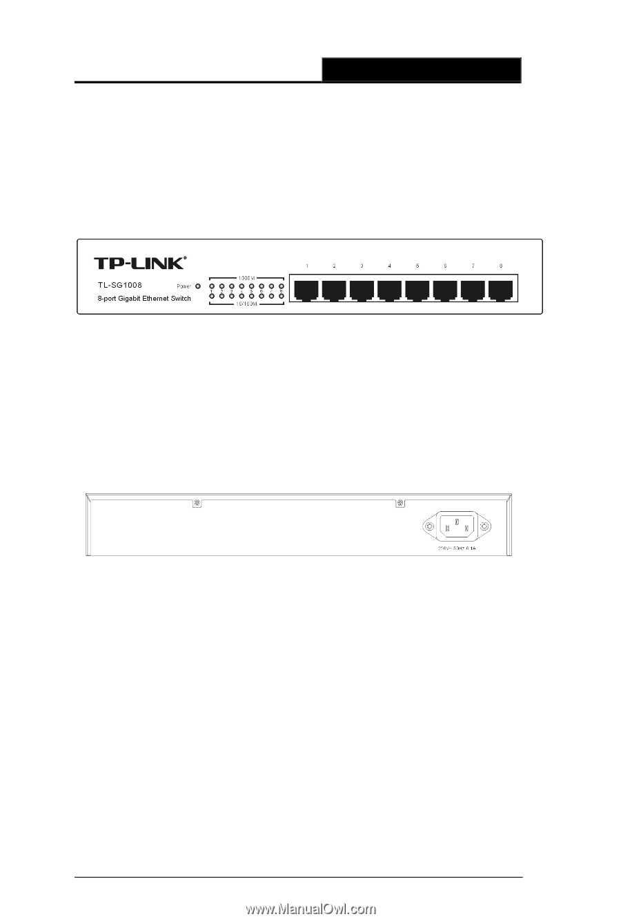
TL-SG1008/TL-SG1016/TL-SG1024/TL-SG1048 Gigabit Ethernet Switch User Guide Chapter 3 Identifying External Components This Chapter describes the front panel, rear panel and LED indicators of the Switch. TL-SG1008, TL-SG1016, TL-SG1024 and TL-SG1048 are different in the number of LED indicators and RJ45 ports. Figure 3-1 TL-SG1008 Switch Front Panel sketch 3.1 Rear Panel The rear panel of the TL-SG1008 only features a power receptacle, which is an AC power receptacle. Connect the female of the power cord head here, and the male head to the AC power outlet. Figure 3-2 TL-SG1008 Switch Rear Panel sketch 3.2 LED Indicators The LED indicators include Power, 1000Mbps Link/Act and 10/100Mbps Link/Act LED indicators, which are used for monitoring and pretroubleshooting of the Switch. The following section shows the LED indicators for the switch along with an explanation of each indicator. 7
-
 1
1 -
2
-
3
-
4
-
5
-
6
-
 7
7 -
 8
8 -
 9
9 -
 10
10 -
 11
11 -
 12
12 -
 13
13 -
 14
14 -
 15
15
 |
 |