TP-Link TL-SL5428E User Guide
TP-Link TL-SL5428E Manual
 |
UPC - 845973020873
View all TP-Link TL-SL5428E manuals
Add to My Manuals
Save this manual to your list of manuals |
TP-Link TL-SL5428E manual content summary:
- TP-Link TL-SL5428E | User Guide - Page 1
TL-SL5428E 24-Port 10/100Mbps + 4-Port Gigabit L2 Managed Switch Rev: 1.0.2 1910010340 - TP-Link TL-SL5428E | User Guide - Page 2
TP-LINK TECHNOLOGIES CO., LTD. Copyright © 2010 TP-LINK TECHNOLOGIES CO., LTD. All rights reserved. http://www.tp-link in accordance with the instruction manual, may cause harmful product may cause radio interference, in which case the user may be required to take adequate measures. SAFETY NOTICES - TP-Link TL-SL5428E | User Guide - Page 3
14 4.3 Console Port ...15 4.4 Power On...16 Chapter 5 Login to the Switch...17 5.1 Login...17 5.2 Configuration ...17 Chapter 6 System ...19 6.1 System Info...19 6.1.1 System Summary 19 6.1.2 Device Description 21 6.1.3 System Time ...22 6.1.4 System IP...23 6.2 User Manage ...24 6.2.1 User Table - TP-Link TL-SL5428E | User Guide - Page 4
6.3.2 Config Backup 26 6.3.3 Firmware Upgrade 27 6.3.4 System Reboot 28 6.3.5 System Reset 28 6.4 Access Security ...28 6.4.1 Access Control 28 6.4.2 SSL Config ...30 6.4.3 SSH Config ...31 Chapter 7 Switching...37 7.1 Port ...37 7.1.1 Port Config ...37 7.1.2 Port Mirror ...38 7.1.3 Port - TP-Link TL-SL5428E | User Guide - Page 5
101 10.1.2 Port Config 102 10.1.3 VLAN Config 103 10.1.4 Multicast VLAN 105 10.2 Multicast IP ...108 10.2.1 Multicast IP Table 109 10.2.2 Static Multicast IP 109 10.3 Multicast Filter...110 10.3.1 IP-Range...111 10.3.2 Port Filter ...112 10.4 Packet Statistics...113 Chapter 11 QoS...115 11 - TP-Link TL-SL5428E | User Guide - Page 6
141 12.4.1 Binding Table 141 12.4.2 Port Binding 141 12.4.3 VLAN Binding 142 Chapter 13 Network Security ...146 13.1 IP-MAC Binding ...146 13.1.1 Binding Table 146 13.1.2 Manual Binding 147 13.1.3 ARP Scanning 149 13.1.4 DHCP Snooping 150 13.2 ARP Inspection ...156 13.2.1 ARP Detect 160 13 - TP-Link TL-SL5428E | User Guide - Page 7
Server 174 Chapter 14 SNMP...176 14.1 SNMP Config ...178 14.1.1 Global Config 178 14.1.2 SNMP View 179 14.1.3 SNMP Group 180 14.1.4 SNMP User 181 14.1.5 SNMP Community 183 14.2 Notification...185 14.3 RMON...187 14.3.1 History Control 188 14.3.2 Event Config 188 14.3.3 Alarm Config 189 - TP-Link TL-SL5428E | User Guide - Page 8
16.2 Log...214 16.2.1 Log Table ...215 16.2.2 Local Log ...215 16.2.3 Remote Log 216 16.2.4 Backup Log 217 16.3 Device Diagnose...218 16.3.1 Cable Test ...218 16.3.2 Loopback ...219 16.4 Network Diagnose ...219 16.4.1 Ping...219 16.4.2 Tracert...220 Chapter 17 System Maintenance via FTP 222 - TP-Link TL-SL5428E | User Guide - Page 9
items should be found in your box: ¾ One L2 managed Switch ¾ One power cord ¾ One console cable ¾ Two mounting brackets and other fittings ¾ Quick Installation Guide ¾ Resource CD for TL-SL5428E switch, including: • This User Guide • Other Helpful Information Note: Make sure that the package - TP-Link TL-SL5428E | User Guide - Page 10
with IT concepts and network terminologies. 1.2 Conventions In this Guide the following conventions are used: ¾ The switch or TL-SL5428E mentioned in this Guide stands for TL-SL5428E 24-Port 10/100Mbps + 4-Port Gigabit L2 Managed Switch without any explanation. ¾ Menu Name→Submenu Name→Tab page - TP-Link TL-SL5428E | User Guide - Page 11
switch. z User Manage: Configure the user name and password for users to log on to the Web management page with a certain access level. z System Tools: Manage the configuration file of the switch access terminal of the Internet Service Provider. z GVRP: GVRP allows the switch to automatically add or - TP-Link TL-SL5428E | User Guide - Page 12
users ordering multicast programs. z Packet Statistics: View the multicast data traffic on each port of the switch, which facilitates you to monitor the IGMP messages in the network. This module is used to configure QoS function to provide different quality of service users IP-MAC Binding: Bind the IP - TP-Link TL-SL5428E | User Guide - Page 13
efficiently. This module is used to configure cluster function to central manage the scattered devices in the network. Here mainly introduces: z from the switch to the destination. Introduces how to download firmware of the switch via FTP function. Lists the glossary used in this manual. Introduces - TP-Link TL-SL5428E | User Guide - Page 14
for choosing the TL-SL5428E 24-Port 10/100Mbps + 4-Port Gigabit L2 Managed Switch! 2.1 Overview of the Switch Designed for workgroups and departments, TL-SL5428E from TP-Link provides wire-speed performance and full set of layer 2 management features. It provides a variety of service features and - TP-Link TL-SL5428E | User Guide - Page 15
+ Supports Telnet, CLI, SNMP v1/v2c/v3, RMON and web access. + Port Mirroring enables monitoring selected ingress/egress traffic. 2.3 Appearance Description 2.3.1 Front Panel Figure 2-1 Front Panel The following parts are located on the front panel of the Switch: ¾ 10/100Mbps Ports: Designed to - TP-Link TL-SL5428E | User Guide - Page 16
features a power socket and a Grounding Terminal (marked with ). Figure 2-2 Rear Panel ¾ Grounding Terminal: TL-SL5428E already comes with Lightning Protection Mechanism. You can also ground the Switch through the PE (Protecting Earth) cable of AC cord or with Ground Cable. For detail information - TP-Link TL-SL5428E | User Guide - Page 17
Location Requirements When you choose a location for the Switch, please follow these guidelines: • Install the Switch on a flat and stable surface that can support the entire weight of the Switch with all fittings. • Locate the Switch far from strong electromagnetic field generators (such as motors - TP-Link TL-SL5428E | User Guide - Page 18
Switch on a flat surface strong enough to support the entire weight of the Switch with all fittings. 2) Remove the adhesive backing papers from the rubber feet. 3) Turnover the Switch Switch. 3.2.2Rack Installation To install the Switch in an EIA standard-sized, 19-inch rack, follow the instructions - TP-Link TL-SL5428E | User Guide - Page 19
, which is also a necessary measure to protect the body from electric shock. In different environments, the Switch may be grounded differently. The following will instruct you to connect the Switch to the ground in two ways, connecting to the Grounding Bar or connecting to the Ground via the power - TP-Link TL-SL5428E | User Guide - Page 20
figure. Figure 3-4 Tips: The Grounding Bar is not provided with our product. • Connecting to the Ground via the power supply If the Switch is installed in the normal environment, the Switch can be grounded via the PE (Protecting Earth)cable of the AC power supply as shown in the following figure. 12 - TP-Link TL-SL5428E | User Guide - Page 21
your situation will comply with the regulation in your country, so they may differ from the figure above. Tips: If you intend to connect the Switch to the ground via the PE (Protecting Earth) cable of AC power cord, please make sure the PE (Protecting Earth) cable in the electrical outlet - TP-Link TL-SL5428E | User Guide - Page 22
shown. Figure 4-1 Connecting the RJ45 Port 4.2 SFP Ports The Switch features two SFP (Small Form-Factor Pluggable) transceiver slots that are valid link on the port, the associated RJ45 port will be disabled and cannot be used. Tips: TL-SL5428E supports 100/1000Base-FX SFP module at full-duplex mode - TP-Link TL-SL5428E | User Guide - Page 23
Note: The serial port of the computer doesn't support plug-and-play feature, please make sure the Switch is powered off before connecting the console cable to the computer. Connect the console port of the Switch and your computer with a console cable as shown in Figure 4-3. Figure 4-3 Connecting the - TP-Link TL-SL5428E | User Guide - Page 24
so they may differ from the figure above. Powering on the Switch, it will automatically initialize and its LED indicators will respond as 1000Mbps LED indicators will flash momentarily and then turn off, which represents a resetting of the system. 2) The PWR LED indicator will light on all the - TP-Link TL-SL5428E | User Guide - Page 25
default address http://192.168.0.1 in the address field of the browser, then press the Enter key. Figure 5-1 Web-browser Tips: To log in to the Switch, the IP the Switch. The IP address is 192.168.0.x ("x" is any number from 2 to 254), Subnet Mask is 255.255.255.0. For the detailed instructions as - TP-Link TL-SL5428E | User Guide - Page 26
Figure 5-3 Main Setup-Menu Note: Clicking Apply can only make the new configurations effective before the switch is rebooted. If you want to keep the configurations effective even the switch is rebooted, please click Saving Config. You are suggested to click Saving Config before cutting off the - TP-Link TL-SL5428E | User Guide - Page 27
configuration of the switch, including four submenus: System Info, User Manage, System Tools and Access Security. 6.1 System Info The System Info, mainly for basic properties configuration, can be implemented on System Summary, Device Description, System Time and System IP - TP-Link TL-SL5428E | User Guide - Page 28
information of the port will be displayed. ¾ Port Info Figure 6-2 Port Information Port: Type: Rate: Status: Displays the port number of the switch. Displays the type of the port. Displays the maximum transmission rate of the port. Displays the connection status of the port. Click a port to - TP-Link TL-SL5428E | User Guide - Page 29
the bandwidth utilization of sending packets on this port. 6.1.2 Device Description On this page you can configure the description of the switch, including device name, device location and system contact. Choose the menu System→System Info→Device Description to load the following page. Figure - TP-Link TL-SL5428E | User Guide - Page 30
Time The following entries are displayed on this screen: ¾ Time Info Current Date: System Current Time Mode: Displays the current date and time of the switch. Displays the current time mode of the switch. ¾ Time Config Manual: When this option is selected, you can set the date and time - TP-Link TL-SL5428E | User Guide - Page 31
Address. You can log on to the Web management page to operate the switch using this IP Address. The switch supports three modes to obtain an IP address: Static IP, DHCP and BOOTP. The IP address obtained using a new mode will replace the original IP address. On this page you can configure the system - TP-Link TL-SL5428E | User Guide - Page 32
not be configured. 5. By default, the default IP address is 192.168.0.1. 6.2 User Manage User Manage functions to configure the user name and password for users to log on to the Web management page with a certain access level so as to protect the settings of the switch from being randomly changed - TP-Link TL-SL5428E | User Guide - Page 33
Select the desired entry to delete the corresponding user information. It is multi-optional The current user information can't be deleted. User ID, Name, Access Level and status: Operation: Displays the current user ID, user name, access level and user status. Click the Edit button of the desired - TP-Link TL-SL5428E | User Guide - Page 34
6.3 System Tools The System Tools function, allowing you to manage the configuration file of the switch, can be implemented on Config Restore, Config Backup, Firmware Upgrade, System Reboot and System Reset pages. 6.3.1 Config Restore On this page you can upload a backup configuration file to - TP-Link TL-SL5428E | User Guide - Page 35
. Please wait without any operation. 6.3.3 Firmware Upgrade The switch system can be upgraded via the Web management page. To upgrade the system is to get more functions and better performance. Go to http://www.tp-link.com to download the updated firmware. Choose the menu System→System Tools - TP-Link TL-SL5428E | User Guide - Page 36
. Figure 6-13 System Reset Note: After the system is reset, the switch will be reset to the default and all the settings will be cleared. 6.4 Access Security Access Security provides different security measures for the remote login so as to enhance the configuration management security. It can be - TP-Link TL-SL5428E | User Guide - Page 37
entries are displayed on this screen: ¾ Access Control Config Control Mode: IP Address&Mask Select the control mode for users to log on to the Web management page. z IP-based: Select this option to limit the IP-range of the users for login. z MAC-based: Select this option to limit the MAC - TP-Link TL-SL5428E | User Guide - Page 38
provides the following services: 1. Authenticate the users and the servers based user to replace the default key pair. After SSL is effective, you can log on to the Web management page via https://192.168.0.1. For the first time you use HTTPS connection to log into the switch with the default - TP-Link TL-SL5428E | User Guide - Page 39
work. 2. The SSL certificate and key downloaded will not take effect until the switch is rebooted. 3. To establish a secured connection using https, please enter https:// to a telnet connection, but essentially the old telnet remote management method is not safe, because the password and data - TP-Link TL-SL5428E | User Guide - Page 40
management being after successful authentication. This switch supports SSH server and you can log on to the switch via SSH connection using SSH supported protocol. Idle Timeout: Specify the idle timeout time. The system will automatically release the connection when the time is up. The default - TP-Link TL-SL5428E | User Guide - Page 41
switch supports three types: SSH-1 RSA, SSH-2 RSA and SSH-2 DSA. Select the desired key file to download. Click the Download button to down the desired key file to the switch the interface of PuTTY. Enter the IP address of the switch into Host Name field; keep the default value 22 in the Port field; - TP-Link TL-SL5428E | User Guide - Page 42
Application Example 2 for SSH: ¾ Network Requirements 1. Log on to the switch via password authentication using SSH and the SSH function is enabled on the switch. 2. PuTTY client software is recommended. ¾ Configuration Procedure 1. Select the key type and key length, and generate SSH key. Note: 1. - TP-Link TL-SL5428E | User Guide - Page 43
3. On the Web management page of the switch, download the public key file saved in the computer to the switch. Note: 1. The key type should accord with the type of the key file. 2. The SSH key downloading can not be interrupted. 4. Download the private key file to SSH client software. 35 - TP-Link TL-SL5428E | User Guide - Page 44
and private key are downloaded, please log on to the interface of PuTTY and enter the IP address for login. After successful authentication, please enter the login user name. If you log on to the switch without entering password, it indicates that the key has been successfully downloaded. Return to - TP-Link TL-SL5428E | User Guide - Page 45
it is in need. The parameters will affect the working mode of the port, please set the parameters appropriate to your needs. Choose the menu Switching→Port→Port Config to load the following page. Figure 7-1 Port Config Here you can view and configure the port parameters. Port Select: Click the - TP-Link TL-SL5428E | User Guide - Page 46
belongs to. Note: 1. The switch can not be managed through the disabled port. Please enable the port which is used to manage the switch. 2. The parameters of the port packets for monitoring and troubleshooting the network. Choose the menu Switching→Port→Port Mirror to load the following page. - TP-Link TL-SL5428E | User Guide - Page 47
Figure 7-2 Mirroring Port The following entries are displayed on this screen. ¾ Mirroring Port Mirroring Port: Select a port from the pull-down list as the mirroring port. When disable is selected, the Port Mirror feature will be disabled. ¾ Mirrored Port Port Select: Click the Select button to - TP-Link TL-SL5428E | User Guide - Page 48
. The attacker uses tools to generate the cheating MAC address and quickly occupy the MAC Address Table. When the MAC Address Table is full, the switch will broadcast the packets to all the ports. At this moment, the attacker can obtain the network information via various sniffers and attacks - TP-Link TL-SL5428E | User Guide - Page 49
can only be deleted manually. The learned entries will be saved even the switch is rebooted. Select 802.1X function is enabled. 7.2 LAG LAG (Link Aggregation Group) is to combine a number of Filtering, Static MAC Address Binding, 802.1X Authentication and IP Source Guard, can not be added to the LAG - TP-Link TL-SL5428E | User Guide - Page 50
ports in the speed of 1000Mbps Full Duplex, the whole bandwidth of the the up-linked speed of 1000Mbps and the down-linked speed of LAG of the switch. Choose the menu Switching→LAG→LAG Table IP + DST IP: When this option is selected, the Aggregate Arithmetic will apply to the source and destination IP - TP-Link TL-SL5428E | User Guide - Page 51
the detailed information of your selected LAG. Figure 7-5 Detail Information 7.2.2 Static LAG On this page, you can manually configure the LAG. The LACP feature is disabled for the member ports of the manually added Static LAG. Choose the menu Switching→LAG→Static LAG to load the following page. 43 - TP-Link TL-SL5428E | User Guide - Page 52
Figure 7-6 Manually Config The following entries are displayed on this screen: ¾ LAG Config Group enables the dynamic link aggregation and disaggregation by exchanging LACP packets with its partner. The switch can dynamically group similarly configured ports into a single logical link, which will - TP-Link TL-SL5428E | User Guide - Page 53
port priorities are equal; the port with smaller port number is preferred. On this page, you can configure the LACP feature of the switch. Choose the menu Switching→LAG→LACP Config to load the following page. Figure 7-7 LACP Config The following entries are displayed on this screen: ¾ Global Config - TP-Link TL-SL5428E | User Guide - Page 54
displays the traffic information of each port, which facilitates you to monitor the traffic and analyze the network abnormity. Choose the menu Switching→Traffic Monitor→Traffic Summary to load the following page. Figure 7-8 Traffic Summary The following entries are displayed on this screen: 46 - TP-Link TL-SL5428E | User Guide - Page 55
Traffic Statistics screen displays the detailed traffic information of each port, which facilitates you to monitor the traffic and locate faults promptly. Choose the menu Switching→Traffic Monitor→Traffic Statistics to load the following page. Figure 7-9 Traffic Statistics 47 - TP-Link TL-SL5428E | User Guide - Page 56
are between 1024 and 2044 bytes. Collisions: Displays the number of collisions experienced by a port during packet transmissions. 7.4 MAC Address The main function of the switch is forwarding the packets to the correct ports based on the 48 - TP-Link TL-SL5428E | User Guide - Page 57
. Address Table contains the port-based MAC address information, which is the base for the switch to forward packets quickly. The entries in the Address Table can be updated by auto-learning or configured manually. Most the entries are generated and updated by auto-learning. In the stable networks - TP-Link TL-SL5428E | User Guide - Page 58
Figure 7-10 Address Table The following entries are displayed on this screen: ¾ Search Option MAC Address: Enter the MAC address of your desired entry. VLAN ID: Enter the VLAN ID of your desired entry. Port: Select the corresponding port number of your desired entry. Type: Select the type of - TP-Link TL-SL5428E | User Guide - Page 59
address table maintains the static address entries which can be added or removed manually, independent of the aging time. In the stable networks, the static MAC address entries can facilitate the switch to reduce broadcast packets and remarkably enhance the efficiency of packets forwarding without - TP-Link TL-SL5428E | User Guide - Page 60
port number of the MAC address is not correct, or the connected port (or the device) has been changed, the switch can not be forward the packets correctly. Please reset the static address entry appropriately. 2. If the MAC address of a device has been added to the Static Address Table, connecting - TP-Link TL-SL5428E | User Guide - Page 61
Figure 7-12 Dynamic Address The following entries are displayed on this screen: ¾ Aging Config Auto Aging: Allows you to Enable/Disable the Auto Aging feature. Aging Time: Enter the Aging Time for the dynamic address. ¾ Search Option Search Option: Select a Search Option from the pull-down - TP-Link TL-SL5428E | User Guide - Page 62
This decreases the forwarding performance of the switch. It is recommended to keep the default value. 7.4.4 Filtering Address The filtering address is to forbid the undesired packets to be forwarded. The filtering address can be added or removed manually, independent of the aging time. The filtering - TP-Link TL-SL5428E | User Guide - Page 63
The following entries are displayed on this screen: ¾ Create Filtering Address MAC Address: Enter the MAC Address to be filtered. VLAN ID: Enter the corresponding VLAN ID of the MAC address. ¾ Search Option Search Option: Select a Search Option from the pull-down list and click the Search - TP-Link TL-SL5428E | User Guide - Page 64
will occupy plenty of bandwidth resources, causing potential serious security problems. A Virtual Local Area Network (VLAN) is a network is, hosts in a VLAN can belong to different physical network segment. This switch supports three ways, namely, 802.1Q VLAN, MAC VLAN and Protocol VLAN, to classify - TP-Link TL-SL5428E | User Guide - Page 65
a packet belongs. When the switch receives an un-VLAN-tagged packet, it will encapsulate a VLAN tag with the default VLAN ID of the inbound port for the packet, and the packet will be assigned to the default VLAN of the inbound port for transmission. In this User Guide, the tagged packet refers to - TP-Link TL-SL5428E | User Guide - Page 66
port belongs to. ¾ PVID PVID (Port Vlan ID) is the default VID of the port. When the switch receives an un-VLAN-tagged packet, it will add a VLAN tag in its default VLAN. Different packets, tagged or untagged, will be processed in different ways, after being received by ports of different link types, - TP-Link TL-SL5428E | User Guide - Page 67
normal communication of the factory switch, the default VLAN of all ports is set to VLAN1. The Web Management Page of switch can only be accessed through ID: Displays the ID number of VLAN. Description: Displays the user-defined description of VLAN. Members: Operation: Displays the port members - TP-Link TL-SL5428E | User Guide - Page 68
VLAN ID you entered is valid or not. ¾ VLAN Members Port Select: Select: Port: Link Type: Click the Select button to quick-select the corresponding entry based on the port number you -optional. Displays the port number. Displays the Link Type of the port. It can be reset on Port Config screen. 60 - TP-Link TL-SL5428E | User Guide - Page 69
: Select the Egress Rule for the VLAN port member. The default egress rule is UNTAG. • TAG: All packets forwarded by Before creating the 802.1Q VLAN, please acquaint yourself with all the devices connected to the switch in order to configure the ports properly. Choose the menu VLAN→802.1Q VLAN→Port - TP-Link TL-SL5428E | User Guide - Page 70
Link Type from the pull-down list for the port. • ACCESS: The ACCESS port can be added in a single VLAN, and the egress rule of the port is UNTAG. The PVID is same as the current VLAN ID. If the current VLAN is deleted, the PVID will be set to 1 by default : Displays the user-defined description of - TP-Link TL-SL5428E | User Guide - Page 71
according to the PVID of the received port. Thus, the packet is assigned automatically to the corresponding VLAN for transmission. 2. When receiving tagged packet, the switch will process it basing on the 802.1Q VLAN. If the received port is the member of the VLAN to which the tagged packet belongs - TP-Link TL-SL5428E | User Guide - Page 72
. MAC Address: Displays the MAC address. Description: Displays the user-defined description of the MAC address. VLAN ID: Displays the feature. All the ports are disabled by default. Configuration Procedure: Step Operation Description 1 Set the link type for Required. On the VLAN→802 - TP-Link TL-SL5428E | User Guide - Page 73
be sorted by IP, IPX, DECnet, AppleTalk, Banyan and so on. Through the Protocol VLANs, the broadcast domain can span over multiple switches and the Host network administrator can manage the network clients basing on their actual applications and services effectively. This switch can classify VLANs - TP-Link TL-SL5428E | User Guide - Page 74
the Modify button to apply your settings. 8.3.2 Protocol Template The Protocol Template should be created before configuring the Protocol VLAN. By default, the switch has defined the IP Template, ARP Template, RARP Template, etc. You can add more Protocol Template on this page. Choose the menu VLAN - TP-Link TL-SL5428E | User Guide - Page 75
following page. Port Enable: Figure 8-11 Enable Protocol VLAN for Port Select your desired port for Protocol VLAN feature. All the ports are disabled by default. 67 - TP-Link TL-SL5428E | User Guide - Page 76
On the VLAN→802.1Q VLAN→Port Config page, set the link type for the port basing on its connected device. 2 Create Service Provider is upgraded, the user's network with a relative independence can still work normally without changing the current configurations. In addition, the switch supports the - TP-Link TL-SL5428E | User Guide - Page 77
outer VLAN tag of this packet with the user-defined value and then send the packet again. Table 1-1as the TPID value. Protocol type ARP IP MPLS IPX IS-IS LACP 802.1X Value 0x0806 0x0800 VPN packets and enable the VPN up-link port. When VPN mode is enabled, the switch will add a tag to the received - TP-Link TL-SL5428E | User Guide - Page 78
port. It's required to set the port connected to the operators' backbone networks to be up-link port. Note: If VPN mode is enabled, please create VLAN Mapping entries on the VLAN Mapping function page. 8.4.2 VLAN Mapping VLAN Mapping function allows the - TP-Link TL-SL5428E | User Guide - Page 79
which the packet received by switch belongs. Enter the ID number of the Service Provider VLAN. Give a ports are disabled for VLAN Mapping function by default. Note: When VPN mode is globally enabled Configure the global TPID. 3 Set the VPN up-link port. Description Required. On the VLAN→VLAN VPN→ - TP-Link TL-SL5428E | User Guide - Page 80
link port. 4 Create VLAN Mapping Required. On the VLAN→VLAN VPN→VLAN Mapping entries. page, configure the VLAN Mapping entries basing on the actual application. 5 Create SP (Service Leave Message: When a GARP entity expects other switches to deregister certain attribute information of its own, - TP-Link TL-SL5428E | User Guide - Page 81
dynamic registration information, which is received from other switches. In this switch, only the port with TRUNK link type can be set as the GVRP application Forbidden mode only permits the packets of the default VLAN (namely VLAN 1) to pass. Choose the menu VLAN→GVRP to load the following page. 73 - TP-Link TL-SL5428E | User Guide - Page 82
Figure 8-15 GVRP Config Note: If the GVRP feature is enabled for a member port of LAG, please ensure all the member ports of this LAG are set to be in the same status and registration mode. The following entries are displayed on this screen: ¾ Global Config GVRP: Allows you to Enable/Disable the - TP-Link TL-SL5428E | User Guide - Page 83
Timer >= 10* Leave Timer, Leave Timer >= 2*Join Timer Configuration Procedure: Step Operation Description 1 Set the link type for port. Required. On the VLAN→802.1Q VLAN→Port Config page, set the link type of the port to be TRUNK. 2 Enable GVRP function. Required. On the VLAN→GVRP page - TP-Link TL-SL5428E | User Guide - Page 84
to IEEE 802.1D standard, is to disbranch a ring network in the Data Link layer in a local network. Devices running STP discover loops in the network and function, the switches in the network transfer BPDUs between each other to exchange information and all the switches supporting STP receive and - TP-Link TL-SL5428E | User Guide - Page 85
1 to 10 seconds. It specifies the interval to send BPDU packets. It is used to test the links. Max. Age: Max. Age ranges from 6 to 40 seconds. It specifies the maximum time the switch can wait without receiving a BPDU before attempting to reconfigure. Forward Delay: Forward Delay ranges from 4 to 30 - TP-Link TL-SL5428E | User Guide - Page 86
is lower than that of the BPDU if of the port itself, the switch discards the BPDU and does not change the BPDU of the port. 2 If port The operation is taken in the following way: Step Operation 1 For each switch (except the one chosen as the root bridge) in a network, the port that - TP-Link TL-SL5428E | User Guide - Page 87
through handshake. ¾ RSTP Elements Edge Port: Indicates the port connected directly to terminals. P2P Link: Indicates the link between two switches directly connected. MSTP (Multiple Spanning Tree Protocol), compatible with both STP and RSTP and subject to IEEE 802.1s standard, not only enables - TP-Link TL-SL5428E | User Guide - Page 88
as STP, MSTP uses BPDUs to generate spanning tree. The only difference is that the BPDU for MSTP carry the MSTP configuration information on the switches. ¾ Port States In an MSTP, ports can be in the following four states: z Forwarding: In this status the port can receive/forward data, receive/send - TP-Link TL-SL5428E | User Guide - Page 89
STP Config, Port Config, MSTP Instance and STP Security. 9.1 STP Config The STP Config function, for global configuration of spanning trees on the switch, can be implemented on STP Config and STP Summary pages. 9.1.1 STP Config Before configuring spanning trees, you should make clear the roles each - TP-Link TL-SL5428E | User Guide - Page 90
10 in seconds to specify the interval to send BPDU packets. It is used to test the links. 2*(Hello Time + 1) ≤ Max Age. The default value is 2 seconds. Enter a value from 6 to 40 in seconds to specify the maximum time the switch can wait without receiving a BPDU before attempting to reconfigure. The - TP-Link TL-SL5428E | User Guide - Page 91
congestions to be falsely regarded as link problems. A too large max age parameter result in the switches unable to find the link problems in time, which in turn handicaps spanning trees being regenerated in time and makes the network less adaptive. The default value is recommended. 4. If the TxHold - TP-Link TL-SL5428E | User Guide - Page 92
Figure 9-5 STP Summary 9.2 Port Config On this page you can configure the parameters of the ports for CIST Choose the menu Spanning Tree→Port Config to load the following page. 84 - TP-Link TL-SL5428E | User Guide - Page 93
Select: Port: Status: Priority: ExtPath: IntPath: Edge Port: P2P Link: MCheck: STP Version: Port Role: Click the Select button to quick- for STP configuration. It is multi-optional. Displays the port number of the switch. Select Enable /Disable STP function for the desired port. Enter a value from - TP-Link TL-SL5428E | User Guide - Page 94
Port: Indicates the port that forwards packets to a downstream network segment or switch. z Master Port: Indicates the port that connects a MST region to the point links. If the physical link of a port is not a point-to-point link and you forcibly configure the link as a point-to-point link, - TP-Link TL-SL5428E | User Guide - Page 95
Figure 9-7 Region Config The following entries are displayed on this screen: ¾ Region Config Region Name: Revision: Create a name for MST region identification using up to 32 characters. Enter the revision from 0 to 65535 for MST region identification. 9.3.2 Instance Config Instance - TP-Link TL-SL5428E | User Guide - Page 96
ID for configuration. It is multi-optional. Displays Instance ID of the switch. Select Enable/Disable the instance. Enter the priority of the switch in the instance. It is an important criterion on determining if the switch will be chosen as the root bridge in the specific instance. Enter the - TP-Link TL-SL5428E | User Guide - Page 97
port number you entered. Select the desired port to specify its priority and path cost. It is multi-optional. Displays the port number of the switch. Enter the priority of the port in the instance. It is an important criterion on determining if the port connected to this port will be - TP-Link TL-SL5428E | User Guide - Page 98
maintains the states of ports by receiving and processing BPDU packets from the upstream switch. However, when link congestions or link failures occurred to the network, a down stream switch does not receive BPDU packets for certain period, which results in spanning trees being regenerated and - TP-Link TL-SL5428E | User Guide - Page 99
blocking state and stops forwarding packets (as if it is disconnected from the link). The port resumes the normal state if it does not receive any configuration these ports do not receive BPDUs, but if a user maliciously attact the switch by sending BPDUs, network topology jitter occurs. To prevent - TP-Link TL-SL5428E | User Guide - Page 100
port for port protect configuration. It is multi-optional. Displays the port number of the switch. Loop Protect is to prevent the loops in the network brought by recalculating STP because of link failures and network congestions. Root Protect is to prevent wrong network topology change caused by - TP-Link TL-SL5428E | User Guide - Page 101
displayed on this screen: ¾ TC Protect TC Threshold: Enter a number from 1 to 100. It is the maximum number of the TC-BPDUs received by the switch in a TC Protect Cycle. The default value is 20. TC Protect Cycle: Enter a value from 1 to 10 to specify the TC Protect Cycle. The - TP-Link TL-SL5428E | User Guide - Page 102
z Switch A, B, C, D and E all support MSTP function. z A is the central switch. z B and C are switches in the convergence layer. D, E and F are switches in revision of MST region page, configure the region as TP-LINK and keep the default revision setting. 4 Configure VLAN-to-Instance On Spanning - TP-Link TL-SL5428E | User Guide - Page 103
, configure the region as TP-LINK and keep the default revision setting. 4 Configure VLAN Switch C: Step Operation Description 1 Configure ports On VLAN→802.1Q VLAN page, configure the link type of the related ports as Trunk, and add the ports to VLAN 101 and VLAN 106. The detailed instructions - TP-Link TL-SL5428E | User Guide - Page 104
Switch D: Step Operation Description 1 Configure ports On VLAN→802.1Q VLAN page, configure the link type of the related ports as Trunk, and add the ports to VLAN 101 and VLAN 106. The detailed instructions , configure the region as TP-LINK and keep the default revision setting. 4 Configure VLAN - TP-Link TL-SL5428E | User Guide - Page 105
¾ Suggestion for Configuration z Enable TC Protect function for all the ports of switches. z Enable Root Protect function for all the ports of root bridges. z Enable Loop Protect function for the non-edge ports. Enable BPDU Protect function or - TP-Link TL-SL5428E | User Guide - Page 106
for networks with densely distributed users. When the number of users requiring this information is not certain, unicast and broadcast deliver a low efficiency. Multicast solves this problem. It can deliver a high efficiency to send data in the point to multi-point service, which can save large - TP-Link TL-SL5428E | User Guide - Page 107
.255.255 Local management multicast addresses, which are used in the local network only Table 10-1 Range of the special multicast IP 2. Multicast MAC packet. If the corresponding entry can not be found in the table, the switch will broadcast the packet in the VLAN owning the receiving port. If the - TP-Link TL-SL5428E | User Guide - Page 108
is mainly for multicast management configuration of the switch, including four submenus: IGMP Snooping, Multicast IP, Multicast Filter and port, its router port time will be directly reset. When receiving IGMP group-specific-query message, the switch will send the group-specific query message to the - TP-Link TL-SL5428E | User Guide - Page 109
port need this multicast and reset the member port time to the leave time. When the leave time times out, the switch will remove the port from not a router port any more. The default value is 300 seconds. Member Port Time: Within the time, if the switch does not receive IGMP report message from the - TP-Link TL-SL5428E | User Guide - Page 110
on this screen: ¾ Global Config IGMP Snooping: Select Enable/Disable IGMP Snooping function globally on the Switch. Unknown Multicast: Select the operation for the switch to process unknown multicast, Forward or Discard. ¾ IGMP Snooping Status Description: Member: Displays IGMP Snooping - TP-Link TL-SL5428E | User Guide - Page 111
If Fast Leave is enabled for a port, the Switch will immediately remove this port from the multicast group upon is effective only when the host supports IGMPv2 or IGMPv3. 2. When both Fast Leave feature of a user connected to a port owning multi-user will result in the other users intermitting the - TP-Link TL-SL5428E | User Guide - Page 112
consider this port is not a router port any more. Member Port Time: Specify the aging time of the member port. Within this time, if the switch doesn't receive IGMP report message from the member port, it will consider this port is not a member port any more. Leave Time: Specify the interval - TP-Link TL-SL5428E | User Guide - Page 113
owning a receiver one copy. This mode wastes a lot of bandwidth. The problem above can be solved by configuring a multicast VLAN. By adding switch ports to the multicast VLAN and enabling IGMP Snooping, you can make users in different VLANs share the same multicast VLAN. This saves the bandwidth - TP-Link TL-SL5428E | User Guide - Page 114
: Specify the aging time of the member port. Within this time, if the switch doesn't receive IGMP report message from the member port, it will consider this port VLAN page. 3. The link type of the member ports in the multicast VLAN can only be GENERAL. 4. Configure the link type of the router port - TP-Link TL-SL5428E | User Guide - Page 115
Config page. Application Example for Multicast VLAN: ¾ Network Requirements Multicast source sends multicast streams via the router, and the streams are transmitted to user A and user B through the switch. Router: Its WAN port is connected to the multicast source; its LAN port is connected to the - TP-Link TL-SL5428E | User Guide - Page 116
pages. For port 3, configure its link type as GENERAL and its egress rule as TAG, and add VLAN as 3 and keep the other parameters as default on Multicast→IGMP Snooping→Multicast VLAN page. 5 IP In a network, receivers can join different multicast groups appropriate to their needs. The switch - TP-Link TL-SL5428E | User Guide - Page 117
Port Displays the forward port of the multicast group. Type: Displays the type of the multicast IP. Note: If the configuration on VLAN Config page and multicast VLAN page is changed, the switch will clear up the dynamic multicast addresses in multicast address table and learn new addresses. 10 - TP-Link TL-SL5428E | User Guide - Page 118
multicast group. ¾ Search Option Search Option: Select the rules for displaying multicast IP table to find the desired entries quickly. z All: Displays all static multicast IP entries. z Multicast IP: Enter the multicast IP address the desired entry must carry. z VLAN ID: Enter the VLAN ID the - TP-Link TL-SL5428E | User Guide - Page 119
to restrict users ordering multicast programs via configuring multicast filter rules. When applying for a multicast group, the host will send IGMP report message. After receiving the report message, the switch will firstly check the multicast filter rules configured for the receiving port. If the - TP-Link TL-SL5428E | User Guide - Page 120
configure the multicast filter rules for port. Take the configuration on this page and the configuration on IP-Range page together to function to implement multicast filter function on the switch. Choose the menu Multicast→Multicast Filter→Port Filter to load the following page. Figure 10-11 Port - TP-Link TL-SL5428E | User Guide - Page 121
→Multicast Filter→IP-Range page. 2 Configure multicast filter Optional. Configure multicast filter rules for ports on rules for ports Multicast→Multicast Filter→Port Filter page. 10.4 Packet Statistics On this page you can view the multicast data traffic on each port of the switch, which - TP-Link TL-SL5428E | User Guide - Page 122
the port number you entered. Port: Displays the port number of the switch. Query Packet: Displays the number of query packets the port received. Report number of IGMPv2 report packets the port received. Report Packet (V3): Displays the number of IGMPv3 report packets the port received. Leave - TP-Link TL-SL5428E | User Guide - Page 123
congested, the problem that many packets complete for resources must be solved, usually in the way of queue scheduling. The switch supports four schedule modes: SP, WRR, SP+WRR and Equ. ¾ Priority Mode This switch implements three priority modes based on port, on 802.1P and on DSCP. By default, the - TP-Link TL-SL5428E | User Guide - Page 124
switch processes untagged packets based on the default priority mode. 3. DSCP Priority Figure 9-3 IP datagram As shown in the figure above, the ToS (Type of Service) in an IP Web management page, you can configure different DS field mapping to the corresponding priority levels. Non-IP datagram with - TP-Link TL-SL5428E | User Guide - Page 125
service time for each queue is not fixed, that is to say, if a queue is empty, the next queue will be scheduled. In this way, the bandwidth resources are made full use of. The default is 1:2:4. In this way, when scheduling queues, the switch allows TC3 to occupy the whole bandwidth following the SP - TP-Link TL-SL5428E | User Guide - Page 126
and then forwards the packets according to specified scheduling algorithms to implement QoS function. This switch implements three priority modes based on port, on 802.1P and on DSCP, and supports four queue scheduling algorithms. The port priorities are labeled as CoS0, CoS1... CoS7. The DiffServ - TP-Link TL-SL5428E | User Guide - Page 127
Required. Log on to the Schedule Mode page to select a schedule mode. 11.1.2 Schedule Mode On this page you can select a schedule mode for the switch. When the network is congested, the problem that many packets complete for resources must be solved, usually in the way of queue scheduling. The - TP-Link TL-SL5428E | User Guide - Page 128
Strict-Priority + Weight Round Robin Mode. In this mode, this switch provides two scheduling groups, SP group and WRR group. Queues ratio of TC0, TC1 and TC2 is 1:2:4. In this way, when scheduling queues, the switch allows TC3 to occupy the whole bandwidth following the SP mode and the TC0, TC1 and - TP-Link TL-SL5428E | User Guide - Page 129
the 802.1P Priority page 2 Enable 802.1P priority Required. By default, the 802.1P priority function is function disabled. 3 Map the 802 definition to IP ToS field given by IEEE. This field is used to divide IP datagram into 64 priorities. When DSCP Priority is enabled, IP datagram are - TP-Link TL-SL5428E | User Guide - Page 130
DSCP Priority. ¾ Priority Level DSCP: Indicates the priority determined by the DS region of IP datagram. It ranges from 0 to 63. Priority Level: Indicates the priority level the packets Priority page 2 Enable DP priority function Required. By default, the DSCP priority function is 122 - TP-Link TL-SL5428E | User Guide - Page 131
disabled. 3 Map the DSCP priority to the Required. Select DSCP priority and the corresponding priority level priority level. 4 Select a schedule mode Required. Log on to the Schedule Mode page to select a schedule mode. 11.2 Bandwidth Control Bandwidth function, allowing you to control the - TP-Link TL-SL5428E | User Guide - Page 132
enabled for one or more ports, you are suggested to disable the flow control on each port to ensure the switch works normally. 11.2.2 Storm Control Storm Control function allows the switch to filter broadcast, multicast and UL frame in the network. If the transmission rate of the three kind packets - TP-Link TL-SL5428E | User Guide - Page 133
. It is multi-optional. Displays the port number of the Switch. Select the bandwidth for receiving broadcast packets on the port. shows the OUI addresses of several manufacturers. The following OUI addresses are preset o the switch by default. Number OUI Address 1 00-01-E3-00-00-00 2 00-03-6B-00- - TP-Link TL-SL5428E | User Guide - Page 134
voice VLAN. Manual Mode: You need to manually add the port of IP phone to voice VLAN, and then the switch will assign ACL supported. stream Manual Mode TAG voice ACCESS: Not supported. stream TRUNK:Supported. The default VLAN of the port should be voice VLAN. GENERAL:Supported. The default - TP-Link TL-SL5428E | User Guide - Page 135
Table 9-2 Port voice VLAN mode and voice stream processing mode ¾ Security Mode of Voice VLAN When voice VLAN is enabled for a port, you can configure its security mode to filter data stream. If security mode is enabled, the port just forwards voice packets, and discards other packets whose source - TP-Link TL-SL5428E | User Guide - Page 136
The following entries are displayed on this screen: ¾ Global Config Voice VLAN: Select Enable/Disable Voice VLAN function. VLAN ID: Enter the VLAN ID of the voice VLAN. Aging Time: Specifies the living time of the member port in auto mode after the OUI address is aging out. Priority: Select - TP-Link TL-SL5428E | User Guide - Page 137
switch automatically adds a port to the voice VLAN or removes a port from the voice VLAN by checking whether the port receives voice data or not z Manual: In this mode, you can manually to. 11.3.3 OUI Config The switch supports OUI create and add the MAC address of the special voice device to the - TP-Link TL-SL5428E | User Guide - Page 138
type of the link type of ports of the voice device. port 2 Create VLAN Required. On VLAN→802.1Q VLAN→Port Config page,, click the Create button to create a VLAN. 3 Add OUI Optional. On QoS→Voice VLAN→OUI Config page, you can check address whether the switch is supporting the OUI template - TP-Link TL-SL5428E | User Guide - Page 139
policies of packets in order to control the access of the illegal users to the network. Besides, ACL functions to control traffic flows and , data packets can be filtered by differentiating the time-ranges. On this switch absolute time, week time and holiday can be configured. Configure an absolute - TP-Link TL-SL5428E | User Guide - Page 140
12.1.2 Time-Range Create On this page you can create time-ranges. Choose the menu ACL→Time-Range→Time-Range Create to load the following page. Figure 12-2 Time-Range Create Note: To successfully configure time-ranges, please firstly specify time-slices and then time-ranges. The following entries - TP-Link TL-SL5428E | User Guide - Page 141
An ACL may contain a number of rules, and each rule specifies a different package range. Packets are matched in match order. Once a rule is matched, the switch processes the matched packets 133 - TP-Link TL-SL5428E | User Guide - Page 142
considering the other rules, which can enhance the performance of the switch. Packets are classified based on match rules in order of the , MAC ACL, Standard-IP ACL and Extend-IP ACL pages. 12.2.1 ACL Summary On this page, you can view the current ACLs configured in the switch. Choose the menu ACL - TP-Link TL-SL5428E | User Guide - Page 143
ID: Enter ACL ID of the ACL you want to create. Rule Order: User Config order is set to be match order in this ACL. 12.2.3 MAC ACL Rule ID: Enter the rule ID. Operation: S-MAC: Select the operation for the switch to process packets which match the 1 rules. z Permit: Forward packets. z Deny: - TP-Link TL-SL5428E | User Guide - Page 144
The following entries are displayed on this screen: ¾ Create Standard-IP ACL ACL ID: Select the desired Standard-IP ACL for configuration. Rule ID: Enter the rule ID. Operation: Fragment: Select the operation for the switch to process packets which match the rules. z Permit: Forward packets - TP-Link TL-SL5428E | User Guide - Page 145
The following entries are displayed on this screen: ¾ Create Extend-IP ACL ACL ID: Select the desired Extend-IP ACL for configuration. Rule ID: Enter the rule ID. Operation: Fragment: Select the operation for the switch to process packets which match the 1 rules. z Permit: Forward packets - TP-Link TL-SL5428E | User Guide - Page 146
port contained in the rule when TCP/UDP is selected from the pull-down list of IP Protocol. Enter the DSCP information contained in the rule. Enter the IP-ToS contained in the rule. Enter the IP Precedence contained in the rule. Select the time-range for the rule to take effect. 12 - TP-Link TL-SL5428E | User Guide - Page 147
¾ Search Option Select Policy: ¾ Action Table Select: Index: ACL ID: S-Mirror: S-Condition: Redirect: QoS Remark: Select name of the desired policy for view. If you want to delete the desired policy, please click the Delete button. Select the desired entry to delete the corresponding policy. Enter - TP-Link TL-SL5428E | User Guide - Page 148
Figure 12-11 Action Create The following entries are displayed on this screen: ¾ Create Action Select Policy: Select the name of the policy. Select ACL: Select the ACL for configuration in the policy. S-Mirror: Select S-Mirror to mirror the data packets in the policy to the specific port. - TP-Link TL-SL5428E | User Guide - Page 149
QoS Remark: Select QoS Remark to forward the data packets based on the QoS settings. z DSCP: Specify the DSCP region for the data packets those match the corresponding ACL. z Local Priority: Specify the local priority for the data packets those match the corresponding ACL. 12.4 Policy Binding - TP-Link TL-SL5428E | User Guide - Page 150
Choose the menu ACL→Policy Binding→Port Binding to load the following page. Figure 12-13 Bind the policy to the port The following entries are displayed on this screen: ¾ Port-Bind Config Policy Name: Select the name of the policy you want to bind. Port: Enter the number of the port you want - TP-Link TL-SL5428E | User Guide - Page 151
bind the policy to the port/VLAN to make the policy effective on the corresponding port/VLAN. Application Example for VLAN Binding: ¾ Network Requirements 1. The manager of the RD department can access to the forum of the company and the Internet without any forbiddance. The MAC address of the - TP-Link TL-SL5428E | User Guide - Page 152
members of VLAN 8. Connect RD department to port 18 of TL-SL5428E, and configure the link type of port 18 as GENERAL and its PVID as 8. The IP range of VLAN 8 is 172.31.50.0. 2 Configure Create page, create a policy named manager.. On ACL→Policy Config→Policy Create page, add ACL 11 to Policy - TP-Link TL-SL5428E | User Guide - Page 153
Config→ACL Create page, create ACL 100. requirement 2 On ACL→ACL Config→Standard-IP ACL page, select ACL 100, and 3 create Rule 1, configure operation as Deny, configure S-IP as 172.31.70.1 and mask as 255.255.255.0, configure D-IP as 172.31.50.1 and mask as 255.255.255.0, configure the time - TP-Link TL-SL5428E | User Guide - Page 154
network access and only allow the Hosts matching the bound entries to access the network. The following three IP-MAC Binding methods are supported by the switch. (1) Manually: You can manually bind the IP address, MAC address, VLAN ID and the Port number together in the condition that you have got - TP-Link TL-SL5428E | User Guide - Page 155
effect. 2 Among the conflicting entries with the same Source priority, only the last added or edited one will take effect. 13.1.2 Manual Binding You can manually bind the IP address, MAC address, VLAN ID and the Port number together in the condition that you have got the related information of the - TP-Link TL-SL5428E | User Guide - Page 156
the Host. Protect Type: Select the Protect Type for the entry. ¾ Manual Binding Table Select: Select the desired entry to be deleted. It is multi-optional. Host Name: Displays the Host Name here. IP Address: Displays the IP Address of the Host. MAC Address: Displays the MAC Address of the - TP-Link TL-SL5428E | User Guide - Page 157
of the Host on Data link layer, is necessary for the packet to reach the very device. So the destination IP address carried in a packet switch to send the ARP request packets of the specified IP field to the Hosts in the LAN or VLAN. Upon receiving the ARP reply packet, the switch can get the IP - TP-Link TL-SL5428E | User Guide - Page 158
Scanning The following entries are displayed on this screen: ¾ Scanning Option Start IP Address: End IP Address: VLAN ID: Scan: Specify the Start IP Address. Specify the End IP Address. Enter the VLAN ID. If blank, the switch will send the untagged packets for scanning. Click the Scan button to - TP-Link TL-SL5428E | User Guide - Page 159
developed basing on the BOOTP, functions to solve the above mentioned problems. ¾ DHCP Working Principle DHCP works via the "Client/Server" Server provides three IP address assigning methods: (1) Manually assign the IP address: Allows the administrator to bind the static IP address to the specific - TP-Link TL-SL5428E | User Guide - Page 160
location of the DHCP Client. Upon receiving the DHCP-REQUEST packet, the switch adds the Option 82 to the packet and then transmits the packet to DHCP security control and account management of Client. The Server supported Option 82 also can set the distribution policy of IP addresses and the other - TP-Link TL-SL5428E | User Guide - Page 161
sub-option should be defined. This Switch supports two sub-options: Circuit ID and problem will happen. The common cases incurring the illegal DHCP servers are the following two: (1) It's common that the illegal DHCP server is manually configured by the user by mistake. (2) Hacker exhausted the IP - TP-Link TL-SL5428E | User Guide - Page 162
Choose the menu Network Security→IP-MAC Binding→Binding Table to load the following page. Figure 13-8 DHCP Snooping Note: If you want to enable the DHCP Snooping feature for the - TP-Link TL-SL5428E | User Guide - Page 163
amount of DHCP messages that can be forwarded by the switch per second. The excessive massages will be discarded. Decline Threshold Decline packets exceeds the Decline Threshold. ¾ Option 82 Config Option 82 Support: Enable/Disable the Option 82 feature. Existed Option 82 field: Select - TP-Link TL-SL5428E | User Guide - Page 164
this false destination MAC address for packets, which results in a breakdown of the normal communication. ¾ Cheating Gateway The attacker sends the wrong IP address-to-MAC address mapping entries of Hosts to the Gateway, which causes that the Gateway can not communicate with the legal terminal Hosts - TP-Link TL-SL5428E | User Guide - Page 165
this false destination MAC address for packets, which results in a breakdown of the normal communication. ¾ Cheating Terminal Hosts The attacker sends the false IP address-to-MAC address mapping entries of terminal Host/Server to another terminal Host, which causes that the two terminal Hosts in the - TP-Link TL-SL5428E | User Guide - Page 166
Figure 13-11 ARP Attack - Cheating Terminal Hosts As the above figure shown, the attacker sends the fake ARP packets of Host A to Host B, and then Host B will automatically update its ARP table after receiving the ARP packets. When Host B tries to communicate with Host A, it will encapsulate this - TP-Link TL-SL5428E | User Guide - Page 167
Figure 13-12 Man-In-The-Middle Attack Suppose there are three Hosts in LAN connected with one another through a switch. Host A: IP address is 192.168.0.101; MAC address is 00-00-00-11-11-11. Host B: IP address is 192.168.0.102; MAC address is 00-00-00-22-22-22. Attacker - TP-Link TL-SL5428E | User Guide - Page 168
ARP Detect ARP Detect feature enables the switch to detect the ARP packets basing on the bound entries in the IP-MAC Binding Table and filter the illegal as up-linked port, routing port and LAG port, should be set as Trusted Port. To ensure the normal communication of the switch, please configure - TP-Link TL-SL5428E | User Guide - Page 169
ID and the connected Port connected Port number of number of the Host together via Manual Binding, ARP the Host together. Scanning or DHCP Snooping. 2 Enable the protection for the Required. On the Network Security→IP-MAC bound entry. Binding→Binding Table page, specify a protect type for the - TP-Link TL-SL5428E | User Guide - Page 170
¾ ARP Defend Port Select: Select: Port: Defend: Speed: Current Speed: Status: LAG: Operation: Click the Select button to quick-select the corresponding port based on the port number you entered. Select your desired port for configuration. It is multi-optional. Displays the port number. Select - TP-Link TL-SL5428E | User Guide - Page 171
Illegal ARP Packet: Displays the number of the received illegal ARP packets. 13.3 IP Source Guard IP Source Guard is to filter the IP packets based on the IP-MAC Binding entries. Only the packets matched to the IP-MAC Binding rules can be processed, which can enhance the bandwidth utility. Choose - TP-Link TL-SL5428E | User Guide - Page 172
to disable the IP Source Guard feature for the port. • SIP: Only the packets with its source IP address and port number matched to the IP-MAC binding rules service requests to the Host, which incurs an abnormal service or even breakdown of the network. With DoS Defend function enabled, the switch - TP-Link TL-SL5428E | User Guide - Page 173
to request disconnection. Therefore, the packet of this type is illegal. The switch can defend this type of illegal packet. Xmascan The attacker sends the legal communication. SYN/SYN-ACK Flooding The attacker uses a fake IP address to send TCP request packets to the Server. Upon receiving - TP-Link TL-SL5428E | User Guide - Page 174
Choose the menu Network Security→DoS Defend→DoS Defend to load the following page. Figure 13-17 DoS Defend The following entries are displayed on this screen: ¾ Defend Config DoS Defend: Allows you to Enable/Disable DoS Defend function. Ping Limiting: Specify the transmission rate of the Ping - TP-Link TL-SL5428E | User Guide - Page 175
Click the Detect button to start the detection. The switch will detect each type of the DoS attack in the network and block the unnecessary network services. 5. Enhance the network security via the LAN ports to solve mainly authentication and security problems. 802.1X is a port-based network access - TP-Link TL-SL5428E | User Guide - Page 176
-supported network device, such as this TP-LINK switch. It provides the physical or logical port for the supplicant system to access the LAN and authenticates the supplicant system. (3) Authentication Server System: The authentication server system is an entity that provides authentication service - TP-Link TL-SL5428E | User Guide - Page 177
to the switch, This TP-LINK switch can support the two fields of EAP: the EAP-message field and the Message-authenticator field. This switch supports user name. 3. The 802.1X client program responds by sending an EAP-Response/Identity packet to the switch with the user name included. The switch - TP-Link TL-SL5428E | User Guide - Page 178
the switch will monitor the status of supplicant by sending hand-shake packets periodically. By default, the switch will is employed between the switch and the RADIUS server. This switch supports the PAP terminating mode PAP mode, the switch encrypts the password and sends the user name, the randomly - TP-Link TL-SL5428E | User Guide - Page 179
network resource. By default, all the ports connected to the supplicants belong to a VLAN, i.e. Guest VLAN. Users belonging to the Guest any response back, the switch will then add these ports into the Guest VLAN according to their link types. Only when the corresponding user passes the 802.1X - TP-Link TL-SL5428E | User Guide - Page 180
from the pull-down list. • EAP-MD5: IEEE 802.1X authentication system uses extensible authentication protocol (EAP) to exchange information between the switch and the client. The EAP protocol packets with authentication data can be encapsulated in the advanced protocol (such as RADIUS) packets to - TP-Link TL-SL5428E | User Guide - Page 181
of the repeated authentication request. Specify the maximum time for the switch to wait for the response from supplicant before resending a request to the supplicant. Specify the maximum time for the switch to wait for the response from authentication server before resending a request - TP-Link TL-SL5428E | User Guide - Page 182
which the port belongs to. 13.5.3 Radius Server RADIUS (Remote Authentication Dial-In User Service) server provides the authentication service for the switch via the stored client information, such as the user name, password, etc, with the purpose to control the authentication and accounting status - TP-Link TL-SL5428E | User Guide - Page 183
. Enable/Disable the accounting feature. Enter the IP address of the accounting server. Enter the IP address of the alternate accounting server. Set the UDP port of accounting server(s). The default port is 1813. Set the shared password for the switch and the accounting servers to exchange messages - TP-Link TL-SL5428E | User Guide - Page 184
Relationship among SNMP Network Elements ¾ SNMP Versions This switch supports SNMP v3, and is compatible with SNMP 1 and SNMP v2c. The SNMP versions adopted by SNMP Management Station and SNMP Agent should be the same. Otherwise, SNMP Management Station and SNMP Agent can not communicate with each - TP-Link TL-SL5428E | User Guide - Page 185
the same. You can configure SNMP Group to control the network access by providing the users in various groups with different management rights via the Read View, Write View and Notify View. 3. Create SNMP User The User is configured in a SNMP Group can manage the switch via the client program on 177 - TP-Link TL-SL5428E | User Guide - Page 186
station. The specified User Name and the Auth/Privacy Password are used for SNMP Management Station to access the SNMP Agent, functioning as the password. SNMP module is used to configure the SNMP function of the switch, including three submenus: SNMP Config, Notification and RMON. 14.1 SNMP - TP-Link TL-SL5428E | User Guide - Page 187
OID (Object Identifier) of the SNMP packets is used to describe the managed objects of the switch, and the MIB (Management Information Base) is the set of the OIDs. The SNMP View is created for the SNMP management station to manage MIB objects. Choose the menu SNMP→SNMP Config→SNMP View to load the - TP-Link TL-SL5428E | User Guide - Page 188
Group to control the network access by providing the users in various groups with different management rights via the Read View, Write View and Notify . SNMP v2c can be configured on the SNMP Community page directly. • v3: SNMPv3 is defined for the group. In this model, the USM mechanism - TP-Link TL-SL5428E | User Guide - Page 189
click the Modify button to apply. Note: Every Group should contain a Read View. The default Read View is viewDefault. 14.1.4 SNMP User The User in a SNMP Group can manage the switch via the management station software. The User and its Group have the same security level and access right. You can - TP-Link TL-SL5428E | User Guide - Page 190
and Security Level. Security Model: Select the Security Model for the User. Security Level: Select the Security Level for the SNMP v3 User. Auth Mode: Auth Password: Select the Authentication Mode for the SNMP v3 User. • None: No authentication method is used. • MD5: The port authentication is - TP-Link TL-SL5428E | User Guide - Page 191
name can limit access to the SNMP agent from SNMP network management station, functioning as a password. If SNMP v1 or SNMP v2c is employed, you can directly configure the SNMP Community on this page without configuring SNMP Group and User. Choose the menu SNMP→SNMP Config→SNMP Community to load the - TP-Link TL-SL5428E | User Guide - Page 192
SNMP Group. 4 Create SNMP User. Description Required. On the SNMP→SNMP Config→Global Config page, enable SNMP function globally. Required. On the SNMP→SNMP Config→SNMP View page, create SNMP View of the management agent. The default View Name is viewDefault and the default OID is 1. Required. On - TP-Link TL-SL5428E | User Guide - Page 193
of the management agent. The default View Name is viewDefault and the default OID is users can manage the device via the Read View, Write View and Notify View defined in the SNMP Group. 14.2 Notification With the Notification function enabled, the switch can initiatively report to the management - TP-Link TL-SL5428E | User Guide - Page 194
with the IP address for the notification sending. The default is 162. User: Enter the User name of the management station. Security Model: Select the Security Model of the management station. Security Level: Type: Retry: Select the Security Level for the SNMP v3 User. • noAuthNoPriv: No - TP-Link TL-SL5428E | User Guide - Page 195
used to send notifications. Displays the User name of the management station. Displays the Security Model of the management station. Displays the Security Level for the SNMP v3 User. Displays the type of the notifications. Displays the maximum time for the switch to wait for the response from the - TP-Link TL-SL5428E | User Guide - Page 196
the history samples were taken. Interval: Specify the interval to take samplings from the port. Owner: Enter the name of the device or user that defined the entry. Status: Select Enable/Disable the corresponding sampling entry. 14.3.2 Event Config On this page, you can configure the RMON - TP-Link TL-SL5428E | User Guide - Page 197
processing. • Log: Logging the event. • Notify: Sending trap messages to the management station. • Log&Notify: Logging the event and sending trap messages to the management station. Enter the name of the device or user that defined the entry. Status: Select Enable/Disable the corresponding event - TP-Link TL-SL5428E | User Guide - Page 198
Figure 14-11 Alarm Config The following entries are displayed on this screen: ¾ Alarm Table Select: Select the desired entry for configuration. Index: Displays the index number of the entry. Variable: Select the alarm variables form the pull-sown list. Port: Select the port on which the - TP-Link TL-SL5428E | User Guide - Page 199
Interval: Owner: Status: Enter the alarm interval time in seconds. Enter the name of the device or user that defined the entry. Select Enable/Disable the corresponding alarm entry. Note: When alarm variables exceed the Threshold on the same direction continuously for several - TP-Link TL-SL5428E | User Guide - Page 200
are needed. The Cluster Management function can solve the above problem. It is mainly used to central manage the scattered devices in the network. A network administrator can manage and maintain the switches in the cluster via a management switch. The management switch is the commander of the - TP-Link TL-SL5428E | User Guide - Page 201
devices to support cluster establishing. An NDP-enabled device sends NDP packets regularly to neighbor devices as well as receives NDP packets from neighbor devices. An NDP packet carries the NDP information (including the device name, MAC address, firmware version and so on). A switch keeps and - TP-Link TL-SL5428E | User Guide - Page 202
Device MAC: Displays MAC address of the neighbor switch. Firmware Version: Displays the firmware version of the neighbor switch. Aging Time: Displays the period for the switch s to keep the NDP packets from the neighbor switch. 15.1.2 NDP Summary On this page you can view the NDP configuration - TP-Link TL-SL5428E | User Guide - Page 203
this screen: ¾ Global Config NDP: Displays the global NDP status (enabled or disabled) for the switch. Aging Time: Displays the period for the neighbor switch to keep the NDP packets from this switch. Hello Time: Displays the interval to send NDP packets. ¾ Port Status Port: Displays the - TP-Link TL-SL5428E | User Guide - Page 204
Detail button to view the complete information collected for the port. 15.1.3 NDP Config On this page you can configure the NDP function for the switch. Choose the menu Cluster→NDP→NDP Config to load the following page. Figure 15-4 NDP Config The following entries are displayed on this screen - TP-Link TL-SL5428E | User Guide - Page 205
which may result in network congestion and the commander switch overload. To avoid the above problem, two time parameters are designed to control the cluster is established, on this page you can manually collect NTDP information at any time to manage and control devices. Choose the menu Cluster→ - TP-Link TL-SL5428E | User Guide - Page 206
the device that is managed in a cluster. z Candidate: Indicates the device that does not belong to any cluster though it can be added to a cluster. z Individual: Indicates the device with cluster feature disabled. Displays the hop count from this device to the switch. Neighbor Info: Click the - TP-Link TL-SL5428E | User Guide - Page 207
the interval to collect topology information. NTDP Hops: Displays the hop count the switch topology collects. NTDP Hop Delay: Displays the time between the switch receiving NTDP request packets and the switch forwarding NTDP request packets for the first time. NTDP Port Delay: Displays the - TP-Link TL-SL5428E | User Guide - Page 208
page. Figure 15-8 NTDP Config The following entries are displayed on this screen: ¾ Global Config NTDP: Select Enable/Disable NTDP for the switch globally. NTDP Interval Time: Enter the interval to collect topology information. The default is 1 minute. NTDP Hops: Enter the hop count the - TP-Link TL-SL5428E | User Guide - Page 209
NDP and NTDP. You can manually add the candidate switch to a cluster. If the candidate switch is successfully added to the cluster, it will get a private IP address assigned by the commander switch. You can manage and configure the member switch via the commander switch. The Cluster function can be - TP-Link TL-SL5428E | User Guide - Page 210
Name: Displays the name of the current cluster the switch belongs to. ¾ Cluster Config IP Pool & Mask: Displays the private IP range of the member switches in the cluster. Hold Time: Displays the time for the commander switch to keep the cluster information. Interval Time: Displays the - TP-Link TL-SL5428E | User Guide - Page 211
Device MAC: Displays the MAC address of the member switch. IP Address: Displays the IP address of the member switch used in the cluster. Status: Displays the connection status of the member switch. Role: Displays the role the switch plays currently. Online Time: Displays the time when the - TP-Link TL-SL5428E | User Guide - Page 212
the role of the switch to be commander switch, and then configure the cluster: z Cluster Name: Configure the name of the current cluster the switch belongs to. z IP Pool & Mask: Configure the private IP range of the member switches in the cluster. z For a commander switch, the following page is - TP-Link TL-SL5428E | User Guide - Page 213
are displayed on this screen: ¾ Current Role Role: Displays the role the current switch plays in the cluster. ¾ Role Change Candidate: Select this option to change the role of the switch to be candidate switch. ¾ Cluster Config Cluster Name: Enter the name of the cluster. Hold Time: Enter - TP-Link TL-SL5428E | User Guide - Page 214
Member Config When this switch is the commander switch of the cluster, via the commander switch you can manually add a candidate switch to the cluster as well as remove the designated member switch from the cluster. On this page you can configure and manage the member switch. Choose the menu Cluster - TP-Link TL-SL5428E | User Guide - Page 215
: Select the desired entry to manage/delete the corresponding member switch. Device Name: Display the description of the member switch. Member MAC: Displays the MAC address of the member switch. IP Address: Displays the IP address of the member switch used in the cluster. Status: Displays - TP-Link TL-SL5428E | User Guide - Page 216
to display the cluster topology. Manage: If the current device is the commander switch in the cluster and the selected device is a member switch in the cluster, you can click the Manage button to log on to Web management page of the corresponding switch. Global configuration procedure of the - TP-Link TL-SL5428E | User Guide - Page 217
switch to view its detailed information; click the icon, and then click the Manage button to log on to its Web management page for configuration. ¾ If the switch is a member switch , the NTDP function on the switch. and then configure NTDP parameters 3 Manually collect NTDP Optional. On Cluster→ - TP-Link TL-SL5428E | User Guide - Page 218
network, port 2 is connecting to member switch 1 and port 3 is connecting to member switch 2. z IP pool: 192.168.0.1, Mask: 255.255.255.0. ¾ Network Diagram Figure 13-19 Network diagram ¾ Configuration Procedure z Configure the member switch Step Operation Description 1 Enable NDP function on - TP-Link TL-SL5428E | User Guide - Page 219
→Member Config page, select the member switch and click the Manage button to log on to its Web management page. Or On Cluster→Cluster→Cluster Topology page, double-click the switch icon to view its detailed information; click the switch icon and click the Manage button to log on to the Web - TP-Link TL-SL5428E | User Guide - Page 220
the commonly used system tools to manage the switch, provides the convenient method to locate and solve the network problem. (1) System Monitor: Monitor the utilization status of the memory and the CPU of switch. (2) Log: View the configuration parameters of the switch and find out the errors via - TP-Link TL-SL5428E | User Guide - Page 221
Figure 16-1 CPU Monitor Click the Monitor button to enable the switch to monitor and display its CPU utilization rate every four seconds. 16.1.2 Memory Monitor Choose the menu Maintenance→System Monitor→Memory Monitor to load the following page. 213 - TP-Link TL-SL5428E | User Guide - Page 222
to monitor and display its Memory utilization rate every four seconds. 16.2 Log The Log system of switch can record, classify and manage the system information effectively, providing powerful support for network administrator to monitor network operation and diagnose malfunction. The Logs of - TP-Link TL-SL5428E | User Guide - Page 223
switch supports logs output to two directions, namely, log buffer and log file. The information in log buffer will be lost after the switch System ->System Info->System Time Web management page. Module: Displays the module the log information saved in switch. By default, all system logs are saved - TP-Link TL-SL5428E | User Guide - Page 224
Table page. It will be lost when the switch is restarted. Log File: Indicates the flash sector for the log file will not be lost after the switch is restarted and can be exported on the Backup . 16.2.3 Remote Log Remote log feature enables the switch to send system logs to the Log Server. Log - TP-Link TL-SL5428E | User Guide - Page 225
Log Host The following entries are displayed on this screen: ¾ Log Host Index: Displays the index of the log host. The switch supports 4 log hosts. Host IP: Configure the IP for the log host. UDP Port: Displays the UDP port used for receiving/sending log information. Here we use the standard - TP-Link TL-SL5428E | User Guide - Page 226
for device diagnose. 16.3.1 Cable Test Cable Test functions to test the connection status of the cable connected to the switch, which facilitates you to locate and diagnose the trouble spot of the network. Choose the menu Maintenance→Device Diagnose→Cable Test to load the following page. Figure 16 - TP-Link TL-SL5428E | User Guide - Page 227
your reference. 16.3.2 Loopback Loopback test function, looping the sender and the receiver of the signal, is used to test whether the port of the switch is available as well as to check and analyze the physical connection status of the port to help you locate and solve network malfunctions. Choose - TP-Link TL-SL5428E | User Guide - Page 228
Ping Config Destination IP: Enter the IP address of the default value is recommended. 16.4.2 Tracert Tracert test function is used to test the connectivity of the gateways during its journey from the source to destination of the test data. When malfunctions occur to the network, you can trouble - TP-Link TL-SL5428E | User Guide - Page 229
Figure 16-10 Tracert The following entries are displayed on this screen: ¾ Tracert Config Destination IP: Enter the IP address of the destination device. Max Hop: Specify the maximum number of the route hops the test data can pass through. Return to CONTENTS 221 - TP-Link TL-SL5428E | User Guide - Page 230
Figure 16-1 1) Connect FTP server to port 1 of the switch. 2) Connect the Console port of the PC to the switch. 3) Save the firmware of the switch in the shared file of FTP server. Please write down the user name, password and the firmware name. 2. Configure the Hyper Terminal After the hardware - TP-Link TL-SL5428E | User Guide - Page 231
Figure 16-2 Open Hyper Terminal 2) The Connection Description Window will prompt shown as Figure 16-3. Enter a name into the Name field and click OK. Figure 16-3 Connection Description 3) Select the port to connect in Figure 16-4 and click OK. 223 - TP-Link TL-SL5428E | User Guide - Page 232
16-5 Port Settings 3. Download Firmware via bootrom menu To download firmware to the switch via FTP function, you need to enter into the bootrom menu of the switch and take the following steps. 1) Connect the console port of the PC to the console port of the switch and open hyper terminal. Connect - TP-Link TL-SL5428E | User Guide - Page 233
. IP address is 172.31.70.146; the user name and password for login to the FTP server are both 123; the name of the upgrade firmware is [TP-LINK] command will display. 7) Please enter start command to start the switch shown as the following figure. Enter the user name and password (the default user - TP-Link TL-SL5428E | User Guide - Page 234
window and you can manage the switch via CLI command. When you forget the login user name and password, you can enter reset command after entering into bootrom menu to reset the system. The system will be restored to the factory default settings, and the default login user name and password are - TP-Link TL-SL5428E | User Guide - Page 235
IEEE802.1p Priority IEEE802.1q VLAN Bridge IEEE802.1X Port-based Access Authentication Ethernet: 10Mbps HD,20Mbps FD Fast Ethernet: 100Mbps HD,200Mbps FD Gigabit Ethernet: 2000Mbps FD 10Base-T: UTP/STP of Cat. 3 or above 100Base-TX: UTP/STP of Cat. 5 100Base-FX: MMF or SMF SFP Module (Optional - TP-Link TL-SL5428E | User Guide - Page 236
correctly in Windows 2000. First make sure your Ethernet Adapter is working, refer to the adapter's manual if necessary. 1. Configure TCP/IP component 1) On the Windows taskbar, click the Start button, and then click Control Panel. 2) Click the Network and Internet Connections icon, and then click - TP-Link TL-SL5428E | User Guide - Page 237
Figure B-2 5) The following TCP/IP Properties window will display and the IP Address tab is open on this window by default. 229 - TP-Link TL-SL5428E | User Guide - Page 238
6) Select Use the following IP address. And the following items will be available. If the switch's IP address is 192.168.0.1, specify IP address as 192.168.0.x (x is from 2 to 254), and the Subnet mask as 255.255.255.0. Now: Click OK to save your settings. Return to CONTENTS 230 - TP-Link TL-SL5428E | User Guide - Page 239
.1X protocol standard for 802.1X authentication. When the switch TL-SL5428E works as the authenticator system, please take the following instructions to install the TpSupplicant provided on the attached CD for the supplicant Client. 1.1 Installation Guide 1. Insert the provided CD into your CD-ROM - TP-Link TL-SL5428E | User Guide - Page 240
To continue, choose the destination location for the installation files and click Next on the following screen. Figure C-4 Choose Destination Location By default, the installation files are saved on the Program Files folder of system disk. Click the Change button to modify the destination location - TP-Link TL-SL5428E | User Guide - Page 241
Figure C-5 Install the Program 6. The InstallShield Wizard is installing TpSupplicant-V2.0 shown as the following screen. Please wait. Figure C-6 Setup Status 7. On the following screen, click Finish to complete the installation. 233 - TP-Link TL-SL5428E | User Guide - Page 242
the TpSupplicant, please take the following steps: 1. On the Windows taskbar, click the Start button, point to All ProgramsÆTP-LINK ÆTpSupplicant-V2.0, and then click Uninstall TP-LINK 802.1X, shown as the following figure. 2. Then the following screen will appear. If you want to stop the remove - TP-Link TL-SL5428E | User Guide - Page 243
4. Click Finish to complete. 1.3 Configuration Figure C-10 Uninstall Complete 1. After completing installation, double click the icon Software. The following screen will appear. to run the TP-LINK 802.1X Client 235 - TP-Link TL-SL5428E | User Guide - Page 244
Figure C-11 TP-LINK 802.1X Client Enter the Name and the Password specified in Start packets to the switch via multicast and send the 802.1X authentication packets via unicast. Obtain an IP address automatically: Select this option if the Client automatically obtains the IP address from DHCP server - TP-Link TL-SL5428E | User Guide - Page 245
period. 3. To continue, click Connect button after entering the Name and Password on Figure C-11. Then the following screen will appear to prompt that the Radius server is being searched. Figure C-13 Authentication Dialog 4. When passing the authentication, the following screen will appear. Figure - TP-Link TL-SL5428E | User Guide - Page 246
: It's because the supported DLL file is missing. You are suggested to go to http://www.winpcap.org to download WinPcap 4.0.2 or the higher version for installation, and run the client software again. Q2: Is this TP-LINK 802.1X Client Software compliable with the switches of the other manufacturers - TP-Link TL-SL5428E | User Guide - Page 247
IP address information, the address of the TFTP server that contains the devices system files, and the name of the boot file. Class of Service (CoS) CoS is supported any device that is plugged into the switch. A user name and password is requested by the switch, and then passed to an authentication - TP-Link TL-SL5428E | User Guide - Page 248
full-duplex links. (Now incorporated in IEEE 802.3-2002) Internet Group Management Protocol (IGMP) A protocol through which hosts can register with their local router for multicast services. If there is more than one multicast switch to report on the IP multicast groups they wish to join or - TP-Link TL-SL5428E | User Guide - Page 249
port is mirrored to a monitor port for troubleshooting with a logic analyzer or RMON probe. This link that combines several lower-speed physical links. Remote Authentication Dial-in User Service users with a cryptographic key, and encrypt data connections between management clients and the switch. 241 - TP-Link TL-SL5428E | User Guide - Page 250
network management services. Simple complicated or backup linked network systems. User Datagram Protocol (UDP) UDP provides a datagram mode for packet-switched communications. It uses IP as the underlying transport mechanism to provide access to IP-like services. UDP packets are delivered just like IP
-
 1
1 -
 2
2 -
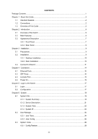 3
3 -
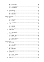 4
4 -
 5
5 -
 6
6 -
 7
7 -
8
-
9
-
10
-
11
-
12
-
13
-
14
-
15
-
16
-
17
-
18
-
19
-
20
-
21
-
22
-
23
-
24
-
25
-
26
-
27
-
28
-
29
-
30
-
31
-
32
-
33
-
34
-
35
-
36
-
37
-
38
-
39
-
40
-
41
-
42
-
43
-
44
-
45
-
46
-
47
-
48
-
49
-
50
-
51
-
52
-
53
-
54
-
55
-
56
-
57
-
58
-
59
-
60
-
61
-
62
-
63
-
64
-
65
-
66
-
67
-
68
-
69
-
70
-
71
-
72
-
73
-
74
-
75
-
76
-
77
-
78
-
79
-
80
-
81
-
82
-
83
-
84
-
85
-
86
-
87
-
88
-
89
-
90
-
91
-
92
-
93
-
94
-
95
-
96
-
97
-
98
-
99
-
100
-
101
-
102
-
103
-
104
-
105
-
106
-
107
-
108
-
109
-
110
-
111
-
112
-
113
-
114
-
115
-
116
-
117
-
118
-
119
-
120
-
121
-
122
-
123
-
124
-
125
-
126
-
127
-
128
-
129
-
130
-
131
-
132
-
133
-
134
-
135
-
136
-
137
-
138
-
139
-
140
-
141
-
142
-
143
-
144
-
145
-
146
-
147
-
148
-
149
-
150
-
151
-
152
-
153
-
154
-
155
-
156
-
157
-
158
-
159
-
160
-
161
-
162
-
163
-
164
-
165
-
166
-
167
-
168
-
169
-
170
-
171
-
172
-
173
-
174
-
175
-
176
-
177
-
178
-
179
-
180
-
181
-
182
-
183
-
184
-
185
-
186
-
187
-
188
-
189
-
190
-
191
-
192
-
193
-
194
-
195
-
196
-
197
-
198
-
199
-
200
-
201
-
202
-
203
-
204
-
205
-
206
-
207
-
208
-
209
-
210
-
211
-
212
-
213
-
214
-
215
-
216
-
217
-
218
-
219
-
220
-
221
-
222
-
223
-
224
-
225
-
226
-
227
-
228
-
229
-
230
-
231
-
232
-
233
-
234
-
235
-
236
-
237
-
238
-
239
-
240
-
241
-
242
-
243
-
244
-
245
-
246
-
247
-
248
-
249
-
250
 |
 |
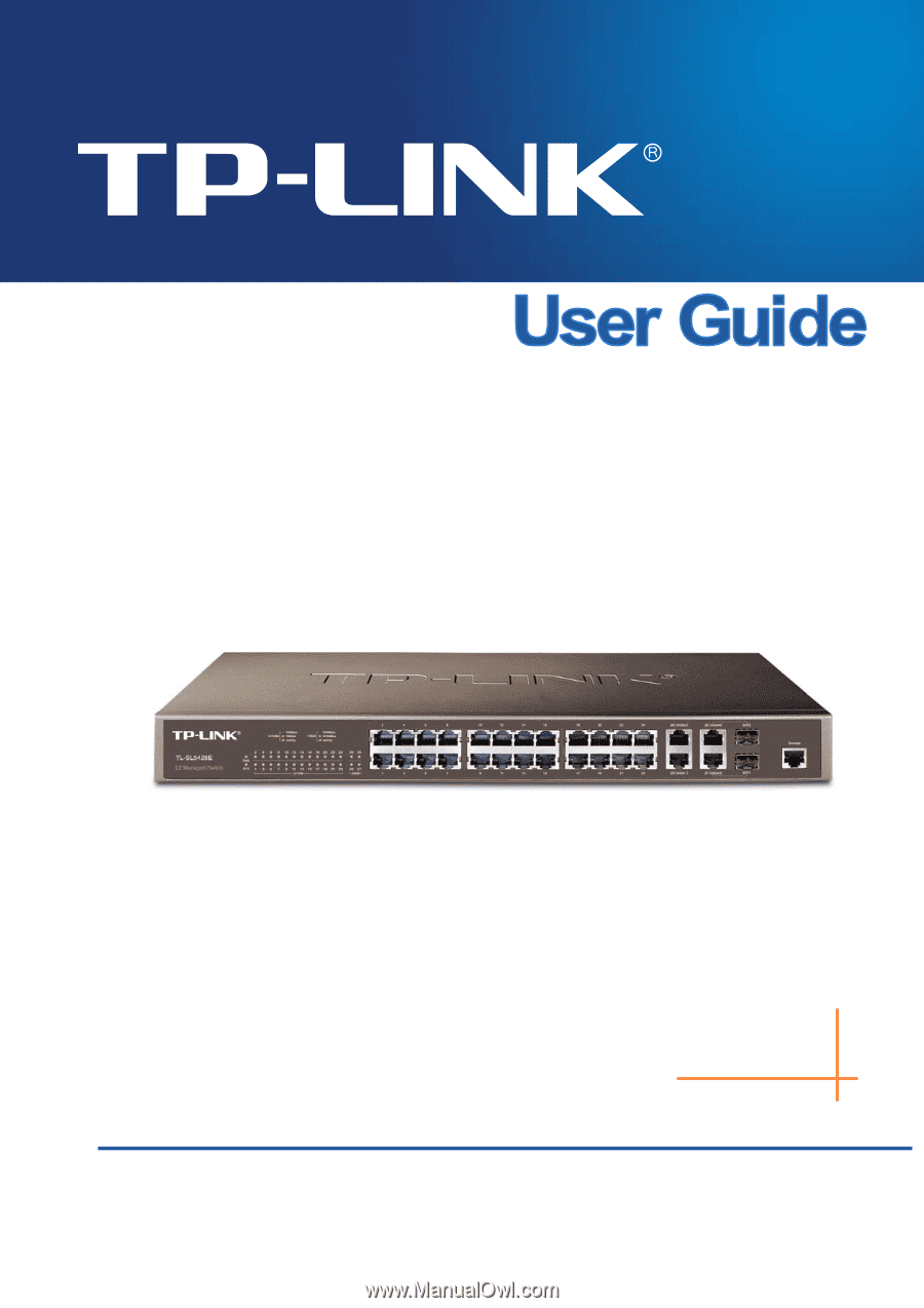
TL-SL5428E
24-Port 10/100Mbps + 4-Port Gigabit
L2 Managed Switch
Rev: 1.0.
2
19100103
4
0