Thermador UCVM36FS Installation Instructions - Page 7
s 3 through 6 are examples of possible ducting
 |
View all Thermador UCVM36FS manuals
Add to My Manuals
Save this manual to your list of manuals |
Page 7 highlights
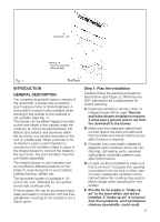
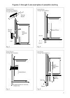
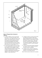
Figures 3 through 6 are examples of possible ducting Remote Blower Roof Mount Installation Through wall installation Remote Blower Integral Blower Through Wall Installation Remote Blower Duct Transition Box Collar Fig. 3 Integral Blower Through Wall Installation Wall Cap Integral Blower Ground Fig. 4 Inline Blower Through Wall Installations Integral Blower Fig. 5 BLOWER ROTATED 90° FOR SIDE CONNECTION Wall Cap Ground Fig. 6 Duct Transition Box Inline Blower 7
-
 1
1 -
 2
2 -
 3
3 -
 4
4 -
 5
5 -
 6
6 -
 7
7 -
 8
8 -
 9
9 -
 10
10 -
 11
11 -
 12
12 -
13
-
14
-
15
-
16
-
17
-
18
-
19
-
20
-
21
-
22
-
23
-
24
-
25
-
26
-
27
-
28
-
29
-
30
-
31
-
32
-
33
-
34
-
35
-
36
-
37
-
38
-
39
-
40
-
41
-
42
-
43
-
44
-
45
-
46
-
47
-
48
 |
 |

Figures 3 through 6 are examples of possible ducting
Fig. 3
Remote Blower
Roof Mount Installation
Through wall installation
Fig. 4
Integral Blower
Through Wall Installation
Fig. 5
Integral Blower
Through Wall Installation
Fig. 6
Inline Blower
Through Wall Installations
7
Remote
Blower
Remote
Blower
Duct
Transition
Box
Collar
Ground
Wall Cap
Duct
Transition
Box
Wall Cap
Ground
Inline
Blower
Integral Blower
BLOWER ROTATED 90° FOR SIDE
CONNECTION
Integral Blower