Thermador VCI29CS Installation Instructions
Thermador VCI29CS Manual
 |
View all Thermador VCI29CS manuals
Add to My Manuals
Save this manual to your list of manuals |
Thermador VCI29CS manual content summary:
- Thermador VCI29CS | Installation Instructions - Page 1
VENTIL ATION INSTALLATION MANUAL MMOODDEELS: CVCVIS22 - Thermador VCI29CS | Installation Instructions - Page 2
Safety 1 Installation 2 Before You Begin 2 Installation Procedure 5 Service 6 Before Calling Service 6 1-800-735-4328 www.thermador.com 5551 McFadden Ave. Huntington Beach, CA 92649 We look forward to hearing from you! - Thermador VCI29CS | Installation Instructions - Page 3
Safety Instructions Appliance Handling Safety Safety Codes and Standards Electric Safety • WARNING: If the information in this manual is not followed exactly, fire or shock may result causing property damage or personal injury. • WARNING: Do not repair or replace any part of the appliance unless - Thermador VCI29CS | Installation Instructions - Page 4
tag, to the service panel. • Be sure your appliance is properly installed and ), and the American Society for Heating, Refrigeration and Air Conditioning Engineers (ASHRAE), and Before You Begin Tools and Parts Needed Parts Included 1. Custom Ventilation Hood and Chimney Assembly 2. Ductwork - Thermador VCI29CS | Installation Instructions - Page 5
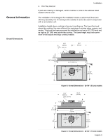
General Information Overall Dimensions 4. One Way Damper Installation If parts are missing or damaged, call the number or write to the address listed inside the front cover. The ventilation unit is designed for installation inside a custom-built hood and chimney assembly. It is for ducting to - Thermador VCI29CS | Installation Instructions - Page 6
a 120V AC, 60Hz. 15A branch circuit. For future service, install the outlet in an easily accessible location. The unit far up in the housing or hood as possible. This will improve the function of the appliance. When calculating the load for the housing support system, be sure to include the - Thermador VCI29CS | Installation Instructions - Page 7
of outside temperatures as part of the ductwork. The service panel and lock the panel to prevent the power from being switched on accidentally. Pull hood from outer packaging. Remove and discard all packaging materials. Remove filter and set aside (See Use and Care manual for removal instructions - Thermador VCI29CS | Installation Instructions - Page 8
instructions. Test the operation of the blower and the lights. Note: Be sure to check for backdraft. With the blower on high, close the windows and doors to the area to ensure that fan does not cause back drafting in any outlet vent for another appliance. See Use and Care Manual for troubleshooting - Thermador VCI29CS | Installation Instructions - Page 9
Service Keep your invoice or escrow papers for warranty validation if service is needed. Data Plate behind filter Figure 10: Data Plate Location English 7 - Thermador VCI29CS | Installation Instructions - Page 10
Sécurit 1 Installation 3 Avant de commencer 3 Méthode d'installation 6 Service 7 Avant d'appeler le service après-vente 7 Questions ? 1-800-735-4328 www.thermador.com 5551 McFadden Ave. Huntington Beach, CA 92649 Nous attendons de vos nouvelles ! - Thermador VCI29CS | Installation Instructions - Page 11
é LIRE ET CONSERVER CES INSTRUCTIONS Instructions de sécurité importantes Conseils de sécurité relatifs à la manipulation de l'appareil Codes et normes de sécurité Sécurité en matière d'électricité • AVERTISSEMENT : si les informations contenues dans ce guide ne sont pas scrupuleusement respect - Thermador VCI29CS | Installation Instructions - Page 12
l'installation, couper le courant au niveau du panneau de service. Fermer le panneau de service à clef pour éviter une mise sous tension accidentelle. Fire Protection Association (NFPA), et l'American Society for Heating, Refrigeration and Air Conditioning Engineers (ASHRAE), et les autorités de - Thermador VCI29CS | Installation Instructions - Page 13
des pièces sont manquantes ou endommagées, appeler le numéro de téléphone ou écrivez à l'adresse figurant à l'intérieur de la couverture du guide. Cet appareil de ventilation est conçu pour une installation à l'intérieur d'un ensemble de hotte aspirante et de cheminée fait sur mesure. Il doit être - Thermador VCI29CS | Installation Instructions - Page 14
ou de la hotte. Ceci permettra à l'appareil de fonctionner de manière plus performante. Lorsque vous calculez la charge pour le système de support du logement, veiller à inclure le poids de l'appareil de ventilation. Voir "Poids de l'appareil de ventilation", page 4. pour obtenir le poids de l'unit - Thermador VCI29CS | Installation Instructions - Page 15
Installation Façonner le logement selon la Figure 7 : Dimensions de découpes du logement modèles de 20 7/8 po (53 cm) ou la Figure 8 : Dimensions de découpes du logement - modèles de 28 3/4 po (73 cm). 5/8" (15 mm) min. (133257./38"mm) 5/8" (15 mm) min. 5/8" (16 mm) (500.139m5m/8)" Figure 7: - Thermador VCI29CS | Installation Instructions - Page 16
choc électrique, couper le courant au niveau du panneau de service et verrouiller le dispositif de sectionnement pour éviter une mise sous Retirer le filtre et mettre de côté (voir le guide d'utilisation et d'entretien pour les instructions de retrait). Préparation du conduit Installer un registre - Thermador VCI29CS | Installation Instructions - Page 17
Installation de l'appareil Service Introduire l'appareil dans le logement jusqu'à ce que les attaches de Figure 9: Installation de l'appareil Installer les filtres. Pour des instructions détaillées, se reporter au Guide d'utilisation et d'entretien. Tester le fonctionnement de la soufflerie - Thermador VCI29CS | Installation Instructions - Page 18
Service Conserver la facture ou tout document pertinent pour la validation de la garantie au cas où une réparation serait nécessaire. Plaque signalétique derrière le filtre Figure 10: Emplacement de la plaque signalétique Français 8 - Thermador VCI29CS | Installation Instructions - Page 19
Seguridad 1 Instalación 3 Antes de empezar 3 Procedimiento de instalación 6 Servicio técnico 7 Antes de llamar al servicio técnico 7 ¿Preguntas? 1-800-735-4328 www.thermador.com 5551 McFadden Ave. Huntington Beach, CA 92649 ¡Esperamos tener noticias suyas pronto! - Thermador VCI29CS | Installation Instructions - Page 20
repare ni cambie ninguna parte del electrodoméstico, a menos que se recomiende específicamente en los manuales. La instalación, servicio electrodomésticos de cocción por microondas (Standard for the Safety of Microwave Cooking Appliances) 3) UL 507, Norma de seguridad para ventiladores eléctricos ( - Thermador VCI29CS | Installation Instructions - Page 21
Protection Association, NFPA) y la Sociedad Americana de Ingenieros en Calefacción, Refrigeración y Aire Acondicionado (American Society for Heating, Refrigeration and Air Conditioning Engineers, ASHRAE) y las autoridades de códigos locales. c) Al cortar o perforar paredes o techos, tenga cuidado - Thermador VCI29CS | Installation Instructions - Page 22
de 6 x 5/8 pulgadas. 4. Regulador de tiro unidireccional Si hay piezas faltantes o dañadas, llame al número o escriba a la dirección que aparecen en la parte interna de la portada. La unidad de ventilación está diseñada para ser instalada dentro de un conjunto de campana y chimenea a medida. Debe - Thermador VCI29CS | Installation Instructions - Page 23
Instalación Preparación Requisitos eléctricos Requisitos de montaje 13 3/4" (348 mm) 6" (150 mm) 13 3/4" (348 mm) 1 3/8" (35 mm) 6 3/8" (160 mm) 3/8" (9 mm) 2 1/8" (55 mm) 28 3/4" (730 mm) 15" (380 mm) 8 7/8" (225 mm) 4" (100 mm) 13 5/8" (346 mm) Figura 6: Dimensiones totales - modelos de - Thermador VCI29CS | Installation Instructions - Page 24
Instalación Construya la carcasa para que coincida con la Figura 7: Dimensiones del hueco para la carcasa - modelos de 20 7/8" (53 cm) o la Figura 8: Dimensiones del hueco para la carcasa - modelos de 28 3/4" (73 cm). 5/8" (15 mm) min. (133257./38"mm) 5/8" (15 mm) min. 5/8" (16 mm) (500.139m5m - Thermador VCI29CS | Installation Instructions - Page 25
rmica no metálica para minimizar la conducción de las temperaturas externas como parte del conducto. El regulador de tiro debe estar en el lado del aire filtro y apártelo (Consulte las instrucciones para retirarlo en el manual de uso y cuidado). Instale un regulador de tiro unidireccional para que - Thermador VCI29CS | Installation Instructions - Page 26
carcasa hasta que los ganchos de plástico que se encuentran en la parte delantera y trasera se cierren a presión en la carcasa. Instale 4 Instale la unidad Instale los filtros. Consulte las instrucciones detalladas en el manual de uso y cuidado. Pruebe el funcionamiento del soplador y de las luces - Thermador VCI29CS | Installation Instructions - Page 27
Servicio técnico Conserve su factura o los papeles de depósito para la validación de la garantía en caso de que necesite solicitar el servicio técnico. Placa de datos detrás del filtro Figura 10: Ubicación de la placa de datos Español 8 - Thermador VCI29CS | Installation Instructions - Page 28
5551 McFadden Avenue, Huntington Beach CA, 92649 • 800-735-4328 • www.thermador.com 9000167402 • 10013 RevB • 03/06 © BSH Home Appliances Corporation • Litho in U.S.A.
-
 1
1 -
 2
2 -
 3
3 -
 4
4 -
 5
5 -
 6
6 -
 7
7 -
8
-
9
-
10
-
11
-
12
-
13
-
14
-
15
-
16
-
17
-
18
-
19
-
20
-
21
-
22
-
23
-
24
-
25
-
26
-
27
-
28
 |
 |

VENTILATION
INSTALLATION MANUAL
MODELS: VCI2