Toshiba A60-S156 User Manual - Page 150
Lift off the cover., Insert the memory module into the connector on the computer. Press
 |
View all Toshiba A60-S156 manuals
Add to My Manuals
Save this manual to your list of manuals |
Page 150 highlights
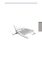
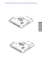
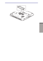
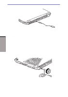
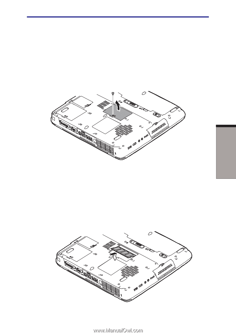
OPTIONAL DEVICES Memory expansion 2. Remove all cables connected to the computer. 3. Turn the computer upside down and remove the battery pack (refer to Chapter 6, Power and Power-Up Modes.) 4. Remove one screw securing the memory module cover. 5. Lift off the cover. NOTE: Use a point size 0 Flippest screwdriver. Figure 8-5 Removing the cover 6. Insert the memory module into the connector on the computer. Press the module carefully and firmly to ensure a solid connection. 7. Push the module down so that it lies flat and is secured by two latches. CAUTION: Do not touch the connectors on the memory module or on the computer. Debris on the connectors may cause memory access problems. Figure 8-6 Inserting the memory module 8-7
-
 1
1 -
2
-
3
-
4
-
5
-
6
-
7
-
8
-
9
-
10
-
11
-
12
-
13
-
14
-
15
-
16
-
17
-
18
-
19
-
20
-
21
-
22
-
23
-
24
-
25
-
26
-
27
-
28
-
29
-
30
-
31
-
32
-
33
-
34
-
35
-
36
-
37
-
38
-
39
-
40
-
41
-
42
-
43
-
44
-
45
-
46
-
47
-
48
-
49
-
50
-
51
-
52
-
53
-
54
-
55
-
56
-
57
-
58
-
59
-
60
-
61
-
62
-
63
-
64
-
65
-
66
-
67
-
68
-
69
-
70
-
71
-
72
-
73
-
74
-
75
-
76
-
77
-
78
-
79
-
80
-
81
-
82
-
83
-
84
-
85
-
86
-
87
-
88
-
89
-
90
-
91
-
92
-
93
-
94
-
95
-
96
-
97
-
98
-
99
-
100
-
101
-
102
-
103
-
104
-
105
-
106
-
107
-
108
-
109
-
110
-
111
-
112
-
113
-
114
-
115
-
116
-
117
-
118
-
119
-
120
-
121
-
122
-
123
-
124
-
125
-
126
-
127
-
128
-
129
-
130
-
131
-
132
-
133
-
134
-
135
-
136
-
137
-
138
-
139
-
140
-
141
-
142
-
143
-
144
-
 145
145 -
 146
146 -
 147
147 -
 148
148 -
 149
149 -
 150
150 -
 151
151 -
 152
152 -
 153
153 -
 154
154 -
 155
155 -
156
-
157
-
158
-
159
-
160
-
161
-
162
-
163
-
164
-
165
-
166
-
167
-
168
-
169
-
170
-
171
-
172
-
173
-
174
-
175
-
176
-
177
-
178
-
179
-
180
-
181
-
182
-
183
-
184
-
185
-
186
-
187
-
188
-
189
-
190
-
191
-
192
-
193
-
194
-
195
-
196
-
197
-
198
-
199
-
200
-
201
-
202
-
203
-
204
-
205
-
206
-
207
-
208
-
209
-
210
-
211
-
212
-
213
-
214
-
215
-
216
-
217
-
218
-
219
-
220
-
221
-
222
-
223
-
224
-
225
-
226
-
227
-
228
-
229
-
230
-
231
-
232
-
233
-
234
-
235
-
236
 |
 |
8-7
O
PTIONAL
D
EVICES
2.
Remove all cables connected to the computer.
3.
Turn the computer upside down and remove the battery pack (refer to Chapter
6,
Power and Power-Up Modes
.)
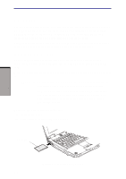
4.
Remove
one screw securing the memory module cover.
5.
Lift off the cover.
NOTE:
Use a point size 0 Flippest screwdriver.
Figure 8-5
Removing the cover
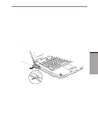
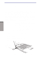
6.
Insert the memory module into the connector on the computer. Press the
module carefully and firmly to ensure a solid connection.
7.
Push the module down so that it lies flat and is secured by two latches.
CAUTION:
Do not touch the connectors on the memory module or on the
computer. Debris on the connectors may cause memory access problems.
Figure 8-6
Inserting the memory module
Memory expansion