Toshiba A600 S2201 Maintenance Manual - Page 173
ODD Bay Module, Replacement Procedures, Disassembling the ODD Drive
 |
UPC - 883974169566
View all Toshiba A600 S2201 manuals
Add to My Manuals
Save this manual to your list of manuals |
Page 173 highlights
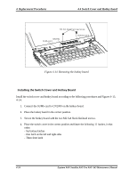
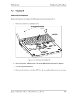
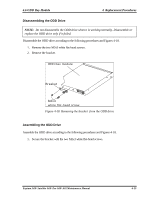
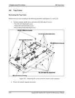
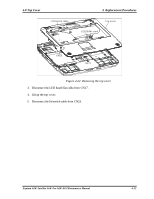
4.6 ODD Bay Module 4 Replacement Procedures Disassembling the ODD Drive NOTE: Do not disassemble the ODD drive when it is working normally. Disassemble or replace the ODD drive only if it failed. Disassemble the ODD drive according to the following procedures and Figures 4-18. 1. Remove the two M2x3 white flat-head screws. 2. Remove the bracket. ODD bay module Breaket M2x3 white flat-head screw Figure 4-18 Removing the bracket from the ODD drive Assembling the ODD Drive Assemble the ODD drive according to the following procedures and Figures 4-18. 1. Secure the bracket with the two M2x3 white flat-head screws. Equium A60/ Satellite A60/ Pro A60/ A65 Maintenance Manual 4-29
-
 1
1 -
2
-
3
-
4
-
5
-
6
-
7
-
8
-
9
-
10
-
11
-
12
-
13
-
14
-
15
-
16
-
17
-
18
-
19
-
20
-
21
-
22
-
23
-
24
-
25
-
26
-
27
-
28
-
29
-
30
-
31
-
32
-
33
-
34
-
35
-
36
-
37
-
38
-
39
-
40
-
41
-
42
-
43
-
44
-
45
-
46
-
47
-
48
-
49
-
50
-
51
-
52
-
53
-
54
-
55
-
56
-
57
-
58
-
59
-
60
-
61
-
62
-
63
-
64
-
65
-
66
-
67
-
68
-
69
-
70
-
71
-
72
-
73
-
74
-
75
-
76
-
77
-
78
-
79
-
80
-
81
-
82
-
83
-
84
-
85
-
86
-
87
-
88
-
89
-
90
-
91
-
92
-
93
-
94
-
95
-
96
-
97
-
98
-
99
-
100
-
101
-
102
-
103
-
104
-
105
-
106
-
107
-
108
-
109
-
110
-
111
-
112
-
113
-
114
-
115
-
116
-
117
-
118
-
119
-
120
-
121
-
122
-
123
-
124
-
125
-
126
-
127
-
128
-
129
-
130
-
131
-
132
-
133
-
134
-
135
-
136
-
137
-
138
-
139
-
140
-
141
-
142
-
143
-
144
-
145
-
146
-
147
-
148
-
149
-
150
-
151
-
152
-
153
-
154
-
155
-
156
-
157
-
158
-
159
-
160
-
161
-
162
-
163
-
164
-
165
-
166
-
167
-
 168
168 -
 169
169 -
 170
170 -
 171
171 -
 172
172 -
 173
173 -
 174
174 -
 175
175 -
 176
176 -
 177
177 -
 178
178 -
179
-
180
-
181
-
182
-
183
-
184
-
185
-
186
-
187
-
188
-
189
-
190
-
191
-
192
-
193
-
194
-
195
-
196
-
197
-
198
-
199
-
200
-
201
-
202
-
203
-
204
-
205
-
206
-
207
-
208
-
209
-
210
-
211
-
212
-
213
-
214
-
215
-
216
-
217
-
218
-
219
-
220
-
221
-
222
-
223
-
224
-
225
-
226
-
227
-
228
-
229
-
230
-
231
-
232
-
233
-
234
-
235
-
236
-
237
-
238
-
239
-
240
-
241
-
242
-
243
-
244
-
245
-
246
-
247
-
248
-
249
-
250
-
251
-
252
-
253
-
254
-
255
-
256
-
257
-
258
-
259
-
260
-
261
-
262
 |
 |

4.6 ODD Bay Module
4
Replacement Procedures
Equium A60/ Satellite A60/ Pro A60/ A65 Maintenance Manual
4-29
Disassembling the ODD Drive
NOTE:
Do not disassemble the ODD drive when it is working normally. Disassemble or
replace the ODD drive only if it failed.
Disassemble the ODD drive according to the following procedures and Figures 4-18.
1.
Remove the two
M2x3 white flat-head screws.
2.
Remove
the
bracket.
ODD bay module
M2x3
white flat-head screw
Breaket
Figure 4-18
Removing the bracket from the ODD drive
Assembling the ODD Drive
Assemble the ODD drive according to the following procedures and Figures 4-18.
1.
Secure the bracket with the two M2x3 white flat-head screws.