Toshiba NB305 PLL3AC-00F014 Users Manual Canada; English - Page 101
Loosen the screw securing the memory module cover.
 |
View all Toshiba NB305 PLL3AC-00F014 manuals
Add to My Manuals
Save this manual to your list of manuals |
Page 101 highlights
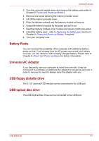
Optional Devices 3. Turn the computer upside down and remove the battery pack - refer to Replacing the battery pack section in Chapter 6, Power and Power-up Modes, if required. 4. Loosen the screw securing the memory module cover. 1 SIM 1. memory module cover Figure 8-2 Removing the memory module cover 5. Align the notch of the memory module with that of the memory module slot and gently insert the module into the slot at about a 30 degree angle before gently pressing until the latches on either side snap into place. ■ Align the grooves along the edges of the memory module with the locking tabs on the connector and insert the memory module into the connector firmly - if you find it difficult to install the memory module, gently prise the locking tabs outwards using the tip of your finger. Please also ensure that you hold the memory module along its left and right hand edges - the edges with the grooves in. User's Manual 8-5
-
 1
1 -
2
-
3
-
4
-
5
-
6
-
7
-
8
-
9
-
10
-
11
-
12
-
13
-
14
-
15
-
16
-
17
-
18
-
19
-
20
-
21
-
22
-
23
-
24
-
25
-
26
-
27
-
28
-
29
-
30
-
31
-
32
-
33
-
34
-
35
-
36
-
37
-
38
-
39
-
40
-
41
-
42
-
43
-
44
-
45
-
46
-
47
-
48
-
49
-
50
-
51
-
52
-
53
-
54
-
55
-
56
-
57
-
58
-
59
-
60
-
61
-
62
-
63
-
64
-
65
-
66
-
67
-
68
-
69
-
70
-
71
-
72
-
73
-
74
-
75
-
76
-
77
-
78
-
79
-
80
-
81
-
82
-
83
-
84
-
85
-
86
-
87
-
88
-
89
-
90
-
91
-
92
-
93
-
94
-
95
-
 96
96 -
 97
97 -
 98
98 -
 99
99 -
 100
100 -
 101
101 -
 102
102 -
 103
103 -
 104
104 -
 105
105 -
 106
106 -
107
-
108
-
109
-
110
-
111
-
112
-
113
-
114
-
115
-
116
-
117
-
118
-
119
-
120
-
121
-
122
-
123
-
124
-
125
-
126
-
127
-
128
-
129
-
130
-
131
-
132
-
133
-
134
-
135
-
136
-
137
-
138
-
139
-
140
-
141
-
142
-
143
-
144
-
145
-
146
-
147
-
148
-
149
-
150
-
151
-
152
 |
 |
