Toshiba SD-2109 Service Manual
Toshiba SD-2109 Manual
 |
View all Toshiba SD-2109 manuals
Add to My Manuals
Save this manual to your list of manuals |
Toshiba SD-2109 manual content summary:
- Toshiba SD-2109 | Service Manual - Page 1
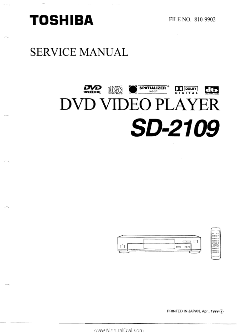
TOSHIBA SERVICE MANUAL FILE NO. 810-9902 410311: 073/t 0COMPACT ir DIGIEDIO SPATIALIZER N-2-2r" DO DOLBY DIGITAL dis DIGITAI OUT DVD VIDEO PLAYER SD2109 O 00 o - ooO000 IMI.0 coo., PRINTED IN JAPAN, Apr., 1999 0 - Toshiba SD-2109 | Service Manual - Page 2
is being turned on, you may not remove this laser cautions label. If it removes, radiation of a laser may be recceived. PREPARATION OF SERVICING Pickup Head consists of a laser diode that is very susceptible to external static electricity. Although it operates properly after replacement, if it was - Toshiba SD-2109 | Service Manual - Page 3
DVD VIDEO PLAYER power plug reversed. NEVER RETURN A DVD VIDEO PLAYER TO THE CUSTOMER WITHOUT TAKING NECESSARY CORRECTIVE ACTION. READING SHOULD NOT EXCEED 0.3V DVD VIDEO PLAYER to alert the user to the presence of important operating and maintenance (servicing) instructions in the literature - Toshiba SD-2109 | Service Manual - Page 4
PC BOARDS FOR SERVICING 2. CIRCUIT SYMBOLS AND SUPPLEMENTARY EXPLANATION 2-1. Precautions for Part Replacement 2-2. Solid Resistor Indication 2-3. Capacitance Indication 2-4. Inductor Indication 2-5. Waveform and Voltage Measurement 2-6. When Replaced ROM ICs or Upgraded Firmware 3. PRINTED WIRING - Toshiba SD-2109 | Service Manual - Page 5
This Digital Video Disc Player employs a Laser System. To ensure proper use of this product, please read this owner's manual carefully and retain for future reference. Should the unit require maintenance, contact an authorized service location see service procedure. Use of controls, adjustments or - Toshiba SD-2109 | Service Manual - Page 6
by the user. DO NOT REMOVE THE CABINET COVER, OR YOU MAY BE EXPOSED TO DANGEROUS VOLTAGE. REFER SERVICING TO QUALIFIED SERVICE PERSONNEL ONLY. 1. Read owner's manual After unpacking this product, read the owner's manual carefully, and follow all the operating and other instructions. 2. Power - Toshiba SD-2109 | Service Manual - Page 7
cause the product and cart combination to overturn. 14. Disc Tray Keep your fingers well clear of the disc tray as it is closing. Neglecting to do so may operating instructions. Adjust only those controls that are covered by the operating instructions as an improper adjustment of other controls may - Toshiba SD-2109 | Service Manual - Page 8
product's instructions. To obtain a clear picture The DVD video player is a high technology, precision device. If the optical pick-up lens and disc drive your nearest dealer. Moisture condensation damages the DVD video player. Please read the following carefully. Moisture condensation occurs, for - Toshiba SD-2109 | Service Manual - Page 9
(PAL, SECAM, etc.). Introduction •SAFETY PRECAUTIONS 2 •IMPORTANT SAFETY INSTRUCTIONS 4 • Precautions 8 • Notes on Discs 9 Notes on region numbers 10 *Table of Contents 11 •Identification of Controls 12 Front panel 12 Rear panel 12 DVD display 13 Remote control 14 Loading - Toshiba SD-2109 | Service Manual - Page 10
VIDEO OUT jacks (Y/Ce/Cv) IE) S VIDEO OUT jack ID Power cord I Power plug 12 DVD display • Pressing of the FL DIMMER button on the remote control changes on the kinds of discs you play. DVD video disc • When closing the disc tray: Example Audio CD • When closing the disc tray: Example Total - Toshiba SD-2109 | Service Manual - Page 11
button to display the menu included on many DVD video discs. To operate a menu, follow the instructions in "Locating a title using the title menu." 24 Loading batteries Open the cover. Operating with the remote control Point the remote control at the remote sensor and press the buttons. 2 Insert - Toshiba SD-2109 | Service Manual - Page 12
to your TV. • Connect the DVD video player directly to your TV. If you connect the DVD video player to a VCR, TVNCR combination or video selector, the playback picture may be distorted as DVD video discs are copy protected. 16 Notes • Refer to the owner's manual of the connected equipment as well - Toshiba SD-2109 | Service Manual - Page 13
AUDIO OUT jack of the DVD video player. • Connect the BITSTREAM/PCM AUDIO OUT jack of the DVD video player to the "COAXIAL' input of a Receiver or Processor. • Refer to the owners manual of the connected equipment as well. • When you connect the DVD video player to other equipment, be sure - Toshiba SD-2109 | Service Manual - Page 14
." ID • There are two different disc sizes. Place the disc in the correct guide on the disc tray. If the disc is out of the guide, it may damage the disc and cause the DVD video player to malfunction. • Do not place anything except DVD video discs or audio CDs on the disc tray. 4 Press PLAY. PLAY - Toshiba SD-2109 | Service Manual - Page 15
TV screen xx xa x30 • To resume normal playback Press PLAY. PLAY Notes • The DVD video player does not play sound and subtitles during reverse and forward scan of DVD video discs. However, the DVD video player plays sound during fast forward or fast reverse play of audio CDs. • The playback speed - Toshiba SD-2109 | Service Manual - Page 16
DVD video disc. If different instructions appear on the TV screen, follow those instructions. • If you display the title menu during playback and press the TITLE button again without selecting any title, the DVD video player . Note Pressing the CLEAR button resets the title and chapter numbers.To - Toshiba SD-2109 | Service Manual - Page 17
at the end of the segment (point B). A-B RPT The DVD video player automatically returns to point A and starts repeat playback of the selected segment (A-B). El To resume normal playback Press CLEAR. CLEAR 8 Notes • Some discs may not permit A-B repeat operation. • You cannot set the A-B repeat - Toshiba SD-2109 | Service Manual - Page 18
to the item you want to change. 2 Change the selection following the instructions in step 2. T Title number or track number C: Chapter number • To • Some discs may not permit memory playback operation. • If you press the REPEAT button during memory playback, the DVD video player repeats the - Toshiba SD-2109 | Service Manual - Page 19
or menus included on DVD video discs. • During zoom playback, the A / V / ► buttons cannot work on menus included on the DVD video discs. If you want to on-screen displays, set "On-Screen Displays" to "Off." ao Monitor the DVD display when you want to change the camera angle. Notes • You can change - Toshiba SD-2109 | Service Manual - Page 20
Notes • When you turn on the DVD video player or replace a disc, player returns la the initial default setting D.. When you select a sound track which is not included on the disc, the DVD video player plays a prior sound track programmed on the disc. • Some discs allow you to change audio selections - Toshiba SD-2109 | Service Manual - Page 21
21. On Current 3-D (N-2-2) setting - Turns off. Bit Role c.0 rrbps Data transfer rate (Mbit/s) Amount of picture, sound and subtitle data in the DVD video disc transferred per second. The larger the value is, the more data processed, but this does not necessarily insure better picture quality - Toshiba SD-2109 | Service Manual - Page 22
Out Select Dynamic Range Control Karaoke Vocal Extended Audio OPERATION Pause/Still Parental Lock Remote Confirmation Title Stop c To DVD video discs may not include your preselected language. In this case, the DVD video player automatically displays disc menus consistent with the disc - Toshiba SD-2109 | Service Manual - Page 23
Select when connected to a 2 channel digital stereo amplifier. is The DVD video player outputs sounds in the PCM 2ch format when you play a DVD video disc recorded on the Dolby Digital. MPEG1 or MPEG2 recording system. Dynamic Range Control c Off: Full dynamic range is maintained. On: Dynamic range - Toshiba SD-2109 | Service Manual - Page 24
a parental lock level and the way a DVD video disc can be controlled may vary from IS) O Some DVD video discs contain special subtitles, an enhancement of closed captioning for hearing impaired persons. The DVD video player disc to disc. For example, if the disc allowed you could edit out violent - Toshiba SD-2109 | Service Manual - Page 25
VO VolapOk WO Wolof XH Xhosa YO Yoruba ZU Zulu Before Calling Service Personnel Check the following guide for the possible cause of a problem before contacting service. Symptoms and correction Symptom No power. The DVD video player turned off by itself. No picture. No sound The playback - Toshiba SD-2109 | Service Manual - Page 26
2. LOCATION OF MAIN PARTS AND MECHANISM PARTS 2-1. Location of Main Parts Feed motor PC board EU02 Power supply PC board EU01 Main PC board EU05 Output PC board EU04 Power SW PC board Disc motor PC board Loading motor PC board Fig. 1-2-1 EU03 Front display PC board 1-22 - Toshiba SD-2109 | Service Manual - Page 27
2-2. Location of Mechanism Parts Tray Clamper stay ink 330 (4 L • Fig. 1-2-2 Mechanism chassis assembly (Top side) it .f! iF ) • Loading motor PC board • Mechanism chassis Fig. 1-2-3 Mechanism chassis assembly (Bottom side) 1-23 - Toshiba SD-2109 | Service Manual - Page 28
Loading belt Kick lever Loading motor • Disc motor Gear Gear Gear Cam Slider Fig. 1-2-4 Mechanism chassis assembly (Internal side) 1 -24 - Toshiba SD-2109 | Service Manual - Page 29
Front damper Front damper Gear A • Gear B assembly Rack gear assembly Rear damper Sub chassis Pickup assembly • • Rear damper Fig. 1-2-5 Pickup mechanism chassis assembly (Top side) "E tAl Feed motor Feed motor PC board Fig. 1-2-6 Pickup mechanism chassis assembly (Bottom side) 1-25 - Toshiba SD-2109 | Service Manual - Page 30
3. TROUBLESHOOTING 3-1. Main Circuit 3-1-1. Servo System (1) Initial Operation NG Disc presence/absence and disc judgement Pin 7 of IC601: LDMN = L Is a disc present? DVD or CD initial setting. Laser OFF Display: INSERT DISC Monitor screen: NO DISC DVD single (single-layer) DVD single - Toshiba SD-2109 | Service Manual - Page 31
switch develops "H", turning off the switch.). Check BUS between IC502 and IC601 and oscillation. Check feed gear. Fig. 1-3-2 2-1 'No disc" misjudgement display of disc presence. Does lens move wit UP/DOWN full stroke in focus direction? 3 Is laser current normal? Does focus search voltage of - Toshiba SD-2109 | Service Manual - Page 32
E522 and E523/3.351 Check peripheral circuits of IC501, Q501 and O502. Check wiring for pickup head. Replace pickup mechanism. Fig. 1-3-5 DVD single (single-layer) disc detection waveform FE signal Pin150 (TP504) of IC502 1.65V SBAD signal Pin152 (TP506) of IC502 t L V : 500 mV/div H : 2 ms/div - Toshiba SD-2109 | Service Manual - Page 33
ON. Yl Focus gain adjustment Tracking gain adjustment Focus balance adjustment Automatic adjustment is carried out when a disc is replaced after power ON. RF gain adjustment Does NG continue more than 3 s.? Disc playback NG Is address code possible to read? Search -- Picture appears. Fig. 1-3-9 - Toshiba SD-2109 | Service Manual - Page 34
motor (D.M.) does not rotate) oes pin 117 of IC502 TP511) PLCK oscillate around 10 MHz? Check peripheral circuits of IC510 and IC503. Check disc motor and wiring. Check peripheral circuit of IC503. Fig. 1-3-10 5 Focus servo is NG. Are FE, SBAD, FSON signals normal? Do signals output to pins - Toshiba SD-2109 | Service Manual - Page 35
=Tripper= Mode Type : EDGE CHO Delay 0.0115 Hold Off MINIMUM ON search 1 Tracking servo on Fig. 1-3-14 Signal waveform at tracking servo ON (DVD) 0100,2 DC 10:1 H2.1V OC In 1 0113.=5V IP 11P1 1090,01./.1.3. m21:.111311 10011.500I,S1s ONO I .Vi\ j/* C OONNONVO, 44,, 4)1# =Filter - Toshiba SD-2109 | Service Manual - Page 36
7 ( Disc playback is NG (DVD). Is PLL locked? Refer to waveforms Check signal process system following to reading RF signal binary data. With the PLL locked, the eye pattern is identified clearly when triggered with the read clock PLCK. DVD playback waveform IV; gki rolgiNteibp, k41,14 44 1'11 DVD - Toshiba SD-2109 | Service Manual - Page 37
3-1-2. Location Diagram of Servo Test Point E594 DMDRV E595 FMDRV E596 TRDRV E597 FODRV ° CN503 IC504 CN502 CN501 IC501 IC502 CN602 IC601 CN801 CN901 IC305 CN301 E523 J.I.11'1130 r ) • '') ;i i 11 ItUR".;;; TP506 RFSB (SBAD) TP505 VREF IC502 TP503 TE TP504 FE Olt TP507 FSON - Toshiba SD-2109 | Service Manual - Page 38
treatment as required. Many screws are used inside the unit. To prevent missing, dropping, etc. of the screws, always use a magnetized screwdriver in servicing. Several kinds of screws are used and some of them need special cautions. That is, take care of the tapping screws securing molded parts and - Toshiba SD-2109 | Service Manual - Page 39
1. The spring for tray side pressure is inserted into the portion "A". (Refer to Fig. 2-1-2.) 2. By referring to Fig. 2-1-3, insert the spring normally and mount the clamper stay. This part should be touch to the left side of the tray. NG O O OK Tray Mechanism chassis assembly - Toshiba SD-2109 | Service Manual - Page 40
Tray (3) Tray panel (4) • After inserting the tray (3), confirm that the mark of the gear (4) matches with that of the rack gear on the tray (first tooth of the gear). (Refer to Fig. B.) Gear (4) Figure A Triangle mark Tray (3) Claws Tray panel (4) Fig. 2-1-5 1-1-4. Front Panel and Tray 1 . - Toshiba SD-2109 | Service Manual - Page 41
1-2. PC Board Replacement 1-2-1. Main PC Board Note: • Before removing the main PC board (4), be sure to short-circuit the laser diode output land. After replacing, open the land as it was after inserting the flexible cables (1). 1. Remove the top cover. (Refer to item 1-1-1.) 2. Remove six flexible - Toshiba SD-2109 | Service Manual - Page 42
1-2-3. Power PC board 1. Peel off the tape ( 1). 2. Remove the connectors (2) and (3). 3. Remove three screws (4). 4. Remove two screws (5). 5. Release two claws and remove the power supply PC board (6). Note: • When mounting, be sure to twist the wire for the connectors (2) and (3) several times. - Toshiba SD-2109 | Service Manual - Page 43
the tray. (Refer to items 1-1-3 and 1-1-4.) 2. Remove three flexible cables (1). 3. Remove four screws (2) and remove the mechanism chassis assembly (3). Screws (2) Pickup head 1-3-2. Loading Belt 1. Remove the gear (1) by releasing the claw. 2. Remove the gear (2). 3. Remove the gear (3) and the - Toshiba SD-2109 | Service Manual - Page 44
the motor with the label positioned as shown in Fig. 2-1-15.) _-- Screws (1) Mechanism chassis assembly Claw - Loading motor (2) N Desolder Claw Motor label side Loading motor PC board (3) Fig. 2-1-15 1-3-4. Sub Chassis (with a pickup mechanism) . Turn the mechanism chassis assembly (1) upside - Toshiba SD-2109 | Service Manual - Page 45
.5D12) 1. When mounting, perform the reverse order of the removal. 2. Mount the gear B assembly (1) by pushing the pickup head (5) to the disc motor side (arrow A direction) and shifting the upper gear of the rack gear assembly (4) in the arrow B direction. (Refer to Fig. 2-1-20.) 3. Fit - Toshiba SD-2109 | Service Manual - Page 46
the reverse order of the removal. Note: • After mounting, put the lead wires through the notch of the pickup mechanism assembly. • When replacing the loading motor, meet the polarity phase of the terminals. (Mount the motor with the label positioned as shown in Fig. 2-1-22.) Screws (1) C Pickup - Toshiba SD-2109 | Service Manual - Page 47
number and description. Parts marked # are of chip type and mounted on original PC boards. However, when they are placed for servicing works, use discrete parts listed on the parts list. ABBREVIATIONS 1. Integrated Circuit (IC) 2. Capacitor (Cap) • Capacitance Tolerance (for Nominal Capacitance - Toshiba SD-2109 | Service Manual - Page 48
4. EXPLODED VIEWS 4-1. Packing Assembly ZK07 ZK03 ZK01 ZF30 ZK04 ZF1 0 ZF11 ZF17 ZF23 ZF20 ZF01 ZK02 Fig. 4-4-1 4-2 - Toshiba SD-2109 | Service Manual - Page 49
4-2. Chassis Assembly ZG60 BID 3.0x6.0 EU02 ZG67 9 ZG63 W503 W502 \\ ZG60 BID 3.0x6.0 ZG64 EU01 W501 / W901 W301 - I O O ZG74 46> ( N EU04 W102 ZG03 EU03 ZG01 ZG70 W602 Fig. 4-4-2 4-3 ZG26 EU05 ZG71 ZG22 - Toshiba SD-2109 | Service Manual - Page 50
4-3. Mechanism Assembly MC03 MC12 MC63 I / BID 2.6x3.5 ..... MC11 I MC14 L RM01 MC61 BID 2.6x8.0 MC04 MPO1 MP61 PAN 2.6x1.5 MP60 PAN 1.7x4.0 MP92 MP37 MP16 MP91 00 am W6.6P0.5D12 r •-• PAN 2.6x8 1 I \ MP37 J L MP36 MC33 MC65 BID 2.6x3.5 MG63 L MP36 FM01 EU05 \- MCO2 W6. - Toshiba SD-2109 | Service Manual - Page 51
Kit B 79070420 Gear Assy,Rack 79070427 Motor Assy,Loading 79080145 Cable,Flexible FFC,4P,L120 79080194 Cable, 170 79078017 Remote Control Unit 79077029 Owners Manual English/Spanish 79077030 Owners Manual French 79070272 Disc DVDZ-9044 79080074 Kit, Data Update LOCATION PART NUMBER - Toshiba SD-2109 | Service Manual - Page 52
LOCATION PART NUMBER NUMBER DESCRIPTION - ELECTRICAL PARTS - IlUEU02 0803 Q821 Q828 AQ802 0822 Q823 Q824 Q825 0826 Q827 Q829 Q830 D802 D803 D804 D805 D806 D807 D810 D811 D812 D821 D822 D823 D824 D825 D826 D827 D828 0829 D830 0831 D832 D833 D834 .L1801 C801 AC802 AC803 C804 C805 AC806 C808 C809 - Toshiba SD-2109 | Service Manual - Page 53
LOCATION PART NUMBER NUMBER DESCRIPTION IC602 79040041 IC PST591-IDT IC607 79040007 IC TC7S08F IC613 79040070 IC S-24CO1AFJ-TB 10614 79040148 IC V53C16128HK-30 IC615 79040153 IC MBM29F8008A55TN IC616 79040007 IC TC7S08F IC617 79040087 IC TC7W241FU IC901 79040151 IC PCM1727E IC902 - Toshiba SD-2109 | Service Manual - Page 54
SPECIFICATIONS DVD Video Player/Outputs/Supplied Accessories [DVD Video Player] Power supply x 1 2.0 V (rms), 220 SI, pin jacks (L,R) x 1 [Supplied Accessories] Audio /video cable 1 Remote control (SE-R0014) 1 Batteries (AA) 2 Power cord 1 * Designs and specifications are subject to
-
 1
1 -
 2
2 -
 3
3 -
 4
4 -
 5
5 -
 6
6 -
 7
7 -
8
-
9
-
10
-
11
-
12
-
13
-
14
-
15
-
16
-
17
-
18
-
19
-
20
-
21
-
22
-
23
-
24
-
25
-
26
-
27
-
28
-
29
-
30
-
31
-
32
-
33
-
34
-
35
-
36
-
37
-
38
-
39
-
40
-
41
-
42
-
43
-
44
-
45
-
46
-
47
-
48
-
49
-
50
-
51
-
52
-
53
-
54
 |
 |
TOSHIBA
SERVICE
MANUAL
FILE
NO.
810-9902
COMPACT
ir
0
SPATIALIZER
DO
DOLBY
N
-2-2r"
410311
:
073/
t
DIGIEDIO
DIGITAL
dis
DIGITAI
OUT
DVD
VIDEO
PLAYER
SD
2109
O
00
o
—
000
IMI.0
ooO
coo.,
PRINTED
IN
JAPAN,
Apr.,
1999
0