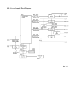
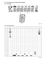
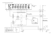
Toshiba SD-2800 Service Manual - Page 4
Inductor Indication, Waveform and Voltage Measurement, 6. Others
 |
View all Toshiba SD-2800 manuals
Add to My Manuals
Save this manual to your list of manuals |
Page 4 highlights
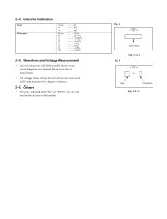
2-4. Inductor Indication Unit Tolerance None m m None B C D F G K M ........... H mH mH 5 0.1 0.25 0.5 1 2 10 20% 2-5. Waveform and Voltage Measurement • The waveforms for CD/DVD and RF shown in the circuit diagrams are obtained when a test disc is played back. • All voltage values except the waveforms are expressed in DC and measured by a digital voltmeter. 2-6. Others • The parts indicated with "NC" or "KETU" etc. are not used in the circuits of this model. Eg. 4 Eg. 5 Type name Fig. 3-2-4 10m Type Tolerance Fig. 3-2-5
-
 1
1 -
 2
2 -
 3
3 -
 4
4 -
 5
5 -
 6
6 -
 7
7 -
 8
8 -
 9
9 -
 10
10 -
11
-
12
-
13
-
14
-
15
-
16
-
17
-
18
-
19
-
20
-
21
-
22
-
23
-
24
-
25
-
26
-
27
-
28
-
29
-
30
-
31
-
32
-
33
-
34
-
35
-
36
-
37
 |
 |
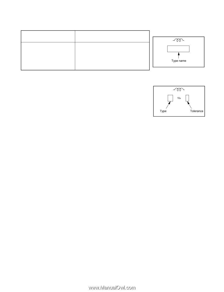
2-4.
Inductor Indication
Unit
None
...........
H
m
...........
m
H
m
...........
mH
Tolerance
None
...........
±5%
B
...........
±0.1%
C
...........
±0.25%
D
...........
±0.5%
F
...........
±1%
G
...........
±2%
K
...........
±10%
M
...........
±20%
2-5.
Waveform and Voltage Measurement
•
The waveforms for CD/DVD and RF shown in the
circuit diagrams are obtained when a test disc is
played back.
•
All voltage values except the waveforms are expressed
in DC and measured by a digital voltmeter.
2-6. Others
•
The parts indicated with "NC" or "KETU" etc. are not
used in the circuits of this model.
Eg. 4
Eg. 5
Fig. 3-2-4
Fig. 3-2-5