Toshiba SD-V291 Owners Manual - Page 10
Toshiba SD-V291 Manual
 |
View all Toshiba SD-V291 manuals
Add to My Manuals
Save this manual to your list of manuals |
Page 10 highlights
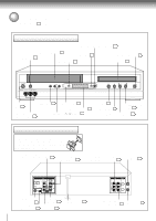
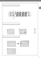
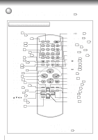
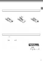
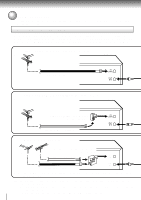
Introduction Identification of controls See the page in for details. Front panel VCR/DVD mode selector button 22 Cassette loading slot 29 DVD indicator 42 EJECT button 29 VCR indicator 22 Disc tray 42 OPEN/CLOSE button 42 ON/STANDBY button 22 REC button 34 Remote sensor 13 Display window 11 STOP button 30 PLAY button 30 FF (Fast Forward) button 30 AUDIO (L/R)/VIDEO IN (LINE IN 2) jacks 40 CHANNEL M/? buttons 34 REW (Rewind) button 30 Rear panel When connecting the optical digital cable, remove the cap and fit the connector into the jack firmly. When not using the jack, keep the cap inserted to protect it from dust intrusion. DVD OPTICAL DIGITAL AUDIO OUT jack (dust protection cap) 20 DVD COAXIAL DIGITAL AUDIO OUT jack 20 DVD/VCR common AUDIO (L/R)/VIDEO OUT jacks 18 RF IN jack 14 DVD S-VIDEO OUT jack 19 S-VIDEO/COMPONENT Video selector switch 19 DVD AUDIO (L/R) OUT jacks 19 AC power cord DVD COMPONENT OUT jacks 19 5 AUDIO (L/R)/VIDEO IN (LINE IN1) jacks 40 RF OUT jack 14 10
-
 1
1 -
2
-
3
-
4
-
 5
5 -
 6
6 -
 7
7 -
 8
8 -
 9
9 -
 10
10 -
 11
11 -
 12
12 -
 13
13 -
 14
14 -
 15
15 -
16
-
17
-
18
-
19
-
20
-
21
-
22
-
23
-
24
-
25
-
26
-
27
-
28
-
29
-
30
-
31
-
32
-
33
-
34
-
35
-
36
-
37
-
38
-
39
-
40
-
41
-
42
-
43
-
44
-
45
-
46
-
47
-
48
-
49
-
50
-
51
-
52
-
53
-
54
-
55
-
56
-
57
-
58
-
59
-
60
-
61
-
62
-
63
-
64
-
65
-
66
-
67
-
68
-
69
-
70
-
71
-
72
 |
 |
