Toshiba Satellite C50D-A PSCFWC-02300G Users Manual Canada; English - Page 36
Underside, Battery pack, Battery release latch, Memory module slot
 |
View all Toshiba Satellite C50D-A PSCFWC-02300G manuals
Add to My Manuals
Save this manual to your list of manuals |
Page 36 highlights
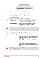
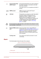
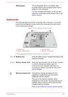
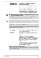
Battery pack The rechargeable lithium-ion battery pack provides power to the computer when the AC adaptor is not connected. For more detailed information on the use and operation of the battery pack please refer to the Battery section. Underside The following figures show the underside of the computer. You should ensure that the display is closed before the computer is turned over to avoid causing any damage. Figure 3-5 The underside of the computer 1 2 4 3 1. Battery lock 2. Battery release latch 3. Cooling vents 4. Memory module slot Product appearance depends on the model you purchased. Battery lock Slide the battery lock to release the battery pack ready for removal. Battery release latch Slide and hold this latch into its "Unlock" position in order to release the battery pack for removal.For more detailed information on removing the battery pack please refer to the Battery section. Memory module slot The memory module slot allows for the installation, replacement and removal of additional memory module. The size of the memory modules varies depending on the model. The actual amount of useable system memory will be less than the installed memory modules. Refer to the Additional memory module section. User's Manual 3-6
-
 1
1 -
2
-
3
-
4
-
5
-
6
-
7
-
8
-
9
-
10
-
11
-
12
-
13
-
14
-
15
-
16
-
17
-
18
-
19
-
20
-
21
-
22
-
23
-
24
-
25
-
26
-
27
-
28
-
29
-
30
-
 31
31 -
 32
32 -
 33
33 -
 34
34 -
 35
35 -
 36
36 -
 37
37 -
 38
38 -
 39
39 -
 40
40 -
 41
41 -
42
-
43
-
44
-
45
-
46
-
47
-
48
-
49
-
50
-
51
-
52
-
53
-
54
-
55
-
56
-
57
-
58
-
59
-
60
-
61
-
62
-
63
-
64
-
65
-
66
-
67
-
68
-
69
-
70
-
71
-
72
-
73
-
74
-
75
-
76
-
77
-
78
-
79
-
80
-
81
-
82
-
83
-
84
-
85
-
86
-
87
-
88
-
89
-
90
-
91
-
92
-
93
-
94
-
95
-
96
-
97
-
98
-
99
-
100
-
101
-
102
-
103
-
104
-
105
-
106
-
107
-
108
-
109
-
110
-
111
-
112
-
113
-
114
-
115
-
116
-
117
-
118
-
119
-
120
-
121
-
122
-
123
-
124
-
125
-
126
-
127
-
128
-
129
-
130
-
131
-
132
-
133
-
134
-
135
-
136
-
137
-
138
-
139
-
140
-
141
 |
 |
