Tripp Lite SMART3000VS Owner's Manual for SmartPro VS UPS 931874 - Page 9
External Battery Connector select models, Input Breakers all models, Output Breakers select models, - battery backup
 |
View all Tripp Lite SMART3000VS manuals
Add to My Manuals
Save this manual to your list of manuals |
Page 9 highlights
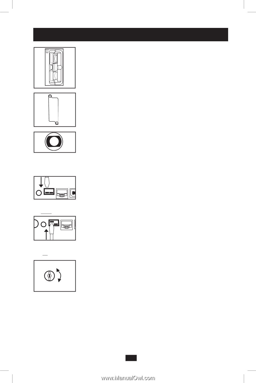
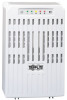
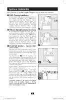
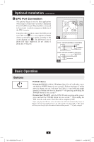
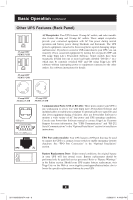
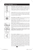
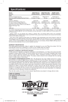
Basic Operation continued External Battery Connector (select models): Use to connect one or more Tripp Lite battery packs for additional runtime. Refer to Specifications and/ or the label next to the connector to determine the appropriate variety of battery pack to use. Refer to the battery pack instruction manual for complete installation information and important safety warnings. See "External Battery Connection" in the "Optional Installation" section. Accessory Slot: Remove the small cover panel from this slot to install optional accessories to remotely monitor and control your UPS. Refer to your accessory's manual for installation instructions. Visit www.tripplite. com for more information, including a list of available SNMP, networking management and connectivity products. Charge Rate Setting (when External Batteries are not connected) Input Breaker(s) (all models): Protect your electrical circuit from overcurrent draw from the UPS load. If these breakers trip, remove some of the load, then reset them by pressing the breaker(s) in. Output Breaker(s) (select models): Your UPS features one or more breakers that protect your UPS from output overload. If one or more breakers trip, remove some of the load on the circuit(s), then reset them by pressing the breaker switch(es) in. Battery Charge Level Switch (select models): Select models feature a switch that controls the UPS system's battery charge rate. If you connect any external batteries, set the Battery Charge Level Switch to the up position. This will increase your UPS's charger output so the additional batteries charge faster. Note: the switch to the right of the Battery Charge Level Switch is inactive and will not affect UPS operation regardless of its position. CAUTION! DO NOT set the Battery Charge Level Switch to the up position without an external battery connected. There is a risk of damaging the UPS's internal battery system. Charge Rate Setting (when External Batteries are connected) NORM DELAY Power Sensitivity Adjustment: This dial is normally set fully counterclockwise, which enables the UPS to provide maximum protection against waveform distortions in its AC input. When such distortion occurs, the UPS will normally switch to providing PWM sine wave power from its battery reserves for as long as the distortion is present. In areas with poor utility power or where the UPS's input power comes from a backup generator, chronic waveform distortion could cause the UPS to switch to battery too frequently, draining its battery reserves. You may be able to reduce how often your UPS switches to battery due to moderate waveform distortion by experimenting with different settings for this dial. As the dial is turned clockwise, the UPS becomes more tolerant of variations in its input power's AC waveform. NOTE: The further the dial is adjusted clockwise, the greater the degree of waveform distortion the UPS will allow to pass to connected equipment. When experimenting with different settings for this dial, operate connected equipment in a safe test mode so that the effect on the equipment of any waveform distortions in the UPS's output can be evaluated without disrupting critical operations. 9 201112099 931874.indb 9 12/28/2011 4:44:10 PM
-
 1
1 -
2
-
3
-
 4
4 -
 5
5 -
 6
6 -
 7
7 -
 8
8 -
 9
9 -
 10
10 -
 11
11 -
 12
12 -
 13
13 -
 14
14 -
15
-
16
-
17
-
18
-
19
-
20
-
21
-
22
-
23
-
24
-
25
-
26
-
27
-
28
-
29
-
30
-
31
-
32
 |
 |