Troy-Bilt Pony CRT Service Manual
Troy-Bilt Pony CRT Manual
 |
View all Troy-Bilt Pony CRT manuals
Add to My Manuals
Save this manual to your list of manuals |
Troy-Bilt Pony CRT manual content summary:
- Troy-Bilt Pony CRT | Service Manual - Page 1
Service Manual Small Frame Troy-Bilt Tillers MTD Products LLC - Product Training and Education Department FORM NUMBER 769-01529 11/2004 - Troy-Bilt Pony CRT | Service Manual - Page 2
- Troy-Bilt Pony CRT | Service Manual - Page 3
TABLE OF CONTENTS Engine: ...1 Forward clutch cable adjustment 1 Forward clutch cable assembly replacement 3 Drive belt replacement 5 Forward return spring replacement 6 Transmission removal: ...7 Transmission disassembly 12 Transmission assembly 21 Forward Idler lever Pivot 32 Reverse clutch - Troy-Bilt Pony CRT | Service Manual - Page 4
- Troy-Bilt Pony CRT | Service Manual - Page 5
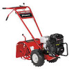
with the Troy-Bilt Factory School. UNIT FEATURES: • 3.75 Hp, 4-cycle engine • Power forward • 14" tilling width • 10" tine diameter • Adjustable tilling depth up to 6" • 10" Agricultural Tires 1. ENGINE: 1.1. Identify the engine that is powering the tiller, and refer to the Engine Owner's Manual for - Troy-Bilt Pony CRT | Service Manual - Page 6
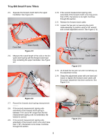
Troy-Bilt Small Frame Tillers 2.5. Squeeze the forward clutch bail to the upper handlebar. See Figure 2.5. 2.10. If the second measurement (spring coils extended) of the forward clutch is too long (more than 3/16"), the tension is too tight. Continue through this section. 2.11. Release the forward - Troy-Bilt Pony CRT | Service Manual - Page 7
measurement procedures to make certain the adjustment is within specifications. 2.16. Tighten the hex jam nut up against the forward clutch cable and ground it to the engine. See Figure 3.1. Spark Plug Troy-Bilt Small Frame Tillers 3.2. Loosen the hex jam nut securing the forward clutch cable - Troy-Bilt Pony CRT | Service Manual - Page 8
Troy-Bilt Small Frame Tillers 3.5. Remove the lower cable tie securing the forward clutch cable to the lower handlebar using side cutters. See Figure 3.5. Cable Tie 3.8. Loosen the hex jam nut securing the forward clutch cable to the lower cable mounting bracket using a 3/8" wrench and a 7/16 3.10 - Troy-Bilt Pony CRT | Service Manual - Page 9
BELT REPLACEMENT: 4.1. Remove the spark plug boot from the spark plug and ground it to the engine. See Figure 4.1. Spark Plug Troy-Bilt Small Frame Tillers 4.4. Remove the belt from the engine drive pulley and forward idler pulley. See Figure 4.4. Drive Pulley Forward Idler Pulley Drive Belt - Troy-Bilt Pony CRT | Service Manual - Page 10
Troy-Bilt Small Frame Tillers 5. FORWARD RETURN SPRING REPLACEMENT: 5.1. Remove the spark plug boot from the spark plug, and ground it to the idler lever. The right lower hole (in the operators position) is used for the Tuffy tiller. 5.6. Install a new return spring in the reverse order above. 6 - Troy-Bilt Pony CRT | Service Manual - Page 11
Troy-Bilt Small Frame Tillers the trailing shield up. Remove Drive Belt 6.10. Remove the hex screw, bushing, lock washer mounting bracket using a 3/8" wrench and a 7/16" wrench. 6.2. Slide the forward clutch cable out hex flange screws securing the tine hood to the right and left hood brackets using - Troy-Bilt Pony CRT | Service Manual - Page 12
Troy-Bilt Small Frame Tillers 6.12. Remove the depth regulator assembly and drag bar assembly. See Figure 6.12. Depth Regulator Assembly 6.14. Raise the front of the tiller unit back onto the tines. NOTE: Make certain the unit is resting on the tines and not on the trailing shield. Hair Pin - Troy-Bilt Pony CRT | Service Manual - Page 13
from the right engine bracket using needle nose pliers. See Figure 6.17. Troy-Bilt Small Frame Tillers 6.20. Remove both sets of hex screws securing the left and right front of the unit and raise it up until the front support can be removed. 6.23. Lower the front of the unit until the pulley/belt guard - Troy-Bilt Pony CRT | Service Manual - Page 14
Troy-Bilt Small Frame Tillers 6.24. Pivot the upper handlebar assembly up until the pulley/belt guard is flat on the floor. See Figure 6.24. Pivoted Forward 6.28 6.26 NOTE: A small pry bar can be used for assistance, if necessary. 6.27. Set the unit on a bench. Figure 6.29 Transmission Pulley 10 - Troy-Bilt Pony CRT | Service Manual - Page 15
Troy-Bilt Small Frame Tillers 6.33. Raise the rear of the transmission up and set it on a 2" x 4" block. See Figure 6.33. Hex Screw & Lock Nut Hex Screw & Lock Nut Front Support and left tine assemblies using a 9/16" socket and wrench. NOTE: Record the orientation of the tine assemblies for - Troy-Bilt Pony CRT | Service Manual - Page 16
Troy-Bilt Small Frame Tillers 6.35. Remove both large drain pan directly in front of the bench. See Figure 7.4. Tine Shaft Wheel Shaft Thoroughly Clean Surfaces GL-4 85W-140 Gear Oil gear oil having a viscosity of SAE 85W-140 (Part Number GW-1360A) or SAE 140. The Tuffy transmission will use approximately? - Troy-Bilt Pony CRT | Service Manual - Page 17
the transmission using a scraper. See Figure 7.8. Wheel Worm Cover Gasket Troy-Bilt Small Frame Tillers 7.10. Remove the rear transmission cover gasket from the transmission using a scraper. See Figure 7.10. Cover Gasket Tine Worm Figure 7.8 7.9. Remove all four hex flange screws securing the - Troy-Bilt Pony CRT | Service Manual - Page 18
Troy-Bilt Small Frame Tillers 7.13. Remove the rear bearing cap from the transmission housing using a scraper. See Figure 7.13. Sealant 7.18. Measure the overall thickness of the rear bearing shims using a dial caliper. See Figure 7.18. Dial Caliper Transmission Housing Rear Bearing Cap Figure 7. - Troy-Bilt Pony CRT | Service Manual - Page 19
Troy-Bilt Small Frame Tillers 7.23. Remove the front tapered roller bearing and support washer, and inspect them for wear or damage. 7.24. Inspect the rear tapered roller bearing assembly for damage or wear. See Figure 7.24. Race Rear Tapered Roller Bearing 7.27. Remove the front tapered roller - Troy-Bilt Pony CRT | Service Manual - Page 20
Troy-Bilt Small Frame Tillers 7.31. Inspect the tiller shaft assembly for wear or damage inside the transmission case. See Figure 7.31. 7.33. Remove the left and right retaining rings securing the wheel shaft in position using medium retaining ring pliers. See Figure 7.33. Tiller Shaft Worm Gear - Troy-Bilt Pony CRT | Service Manual - Page 21
at the end work well for external shim removal. See Image Below Troy-Bilt Small Frame Tillers 7.38. Drive the wheel shaft to the right, forcing the Ways 7.40. Slide the wheel shaft back into the housing until the Hi-Pro key contacts the wheel shaft worm gear. 7.41. Rotate the wheel shaft worm gear - Troy-Bilt Pony CRT | Service Manual - Page 22
Troy-Bilt Small Frame Tillers 7.42. Drive the wheel shaft to the left, forcing the bronze wheel shaft bushing out of the transmission housing using a block of wood and a large hammer. See Figure 7.42. 7.45. Remove the Hi-Pro key from the wheel shaft using a punch and a hammer. See Figure 7.45. - Troy-Bilt Pony CRT | Service Manual - Page 23
an oil seal removal tool. See Figure 7.47. Oil Seal Troy-Bilt Small Frame Tillers 7.49. Remove the external shims from the right and left hand sides of the tine shaft using a small hook tool and a stick magnet. See Figure 7.49. Tine Shaft Tine Shaft Figure 7.47 7.48. Remove the left and right - Troy-Bilt Pony CRT | Service Manual - Page 24
Troy-Bilt Small Frame Tillers 7.52. Drive the tiller shaft to the left, forcing the bronze tiller shaft bushing out of the transmission housing using a block of wood and a large hammer. See Figure 7.52. Spacer Hammer 2" x 4" Bronze Bushing Tiller Shaft Figure 7.52 NOTE: The inner spacer will be - Troy-Bilt Pony CRT | Service Manual - Page 25
housing for wear or damage. See Figure 7.61. Troy-Bilt Small Frame Tillers 8.3. Make certain all the drive shaft components are vice that is lined with a protective material. See Figure 8.2. Transmission Housing Protective Material Tapered Roller Bearing Race Shims Rear Bearing Cap Short - Troy-Bilt Pony CRT | Service Manual - Page 26
Troy-Bilt Small Frame Tillers 8.5. Locate two sets of miscellaneous flat washers that would equal approximately.120" Thicknesses Tapered Roller Bearing Support Washer Figure 8.8 8.9. Slide the support washer and front tapered roller bearing onto the drive shaft assembly. 8.10. Slide the drive - Troy-Bilt Pony CRT | Service Manual - Page 27
tapered roller bearing race over the rear tapered roller bearing. See Figure 8.11. Troy-Bilt Small Frame Tillers 8.15. Pull the drive shaft assembly forward all the way, and set up a dial indicator at the front end. See Figure 8.15. Magnetic Base Rear Tapered Roller Bearing Race Figure 8.11 8.12 - Troy-Bilt Pony CRT | Service Manual - Page 28
Troy-Bilt Small Frame Tillers 8.18. Identify rear bearing cap shims that have a total stack tolerance thickness that is equal to the drive shaft assembly end play, minus .005" to .015" using a dial caliper. See Figure 8.18. Dial Caliper 8.22. Set the rear bearing cap gasket and shim aside. NOTE: - Troy-Bilt Pony CRT | Service Manual - Page 29
Troy-Bilt Small Frame Tillers 8.31. If the drive shaft assembly end play is not within tolerance Pipe Hex Flange Screws Drive Shaft Assembly Snap Ring Support Washer 7" Long Rear Tapered Roller Bearing Race Rear Bearing Cap Shims Rear Bearing Cap Race Short Hex Screw Front Tapered Roller - Troy-Bilt Pony CRT | Service Manual - Page 30
Troy-Bilt Small Frame Tillers 8.35. Drive the Hi-Pro key into the wheel shaft using a soft mallet. See Figure 8.35. 8.41. Drive the second wheel shaft bronze bushing into the transmission housing until it - Troy-Bilt Pony CRT | Service Manual - Page 31
8.45. Push the wheel shaft in the opposite direction until it comes to a stop. See Figure 8.45. Troy-Bilt Small Frame Tillers 8.49. Measure the wheel shaft end play using the above procedures. See Figure 8.49. Push Wheel Shaft In Dial Indicator Figure 8.45 8.46. Record the - Troy-Bilt Pony CRT | Service Manual - Page 32
Troy-Bilt Small Frame Tillers 8.58. Lubricate the insides of the wheel shaft oil seals with the above wheel shaft oil seal installation procedures for the opposite side. 8.66. Drive one of the tine shaft's bronze bushings into the transmission housing until it is flush with the inside of the housing - Troy-Bilt Pony CRT | Service Manual - Page 33
shaft through the opposite bushing bore, through the tiller shaft worm gear and spacer, and into the installed tine shaft bronze bushing. See Figure 8.69. Spacer Spacer Bronze Bushing Troy-Bilt Small Frame Tillers 8.74. Drive the first tine shaft bronze bushing into the transmission housing until - Troy-Bilt Pony CRT | Service Manual - Page 34
Troy-Bilt Small Frame Tillers 8.79. Split the recorded tine shaft end play, and install equal thickness external shims onto the wheel shaft. See Figure 8.79. External Shims 8.88. If the tine shaft end play is not within tolerance, perform the above procedures until it is correct. NOTE: Shims of - Troy-Bilt Pony CRT | Service Manual - Page 35
Troy-Bilt Small Frame Tillers 8.96. Drive the tine shaft seal into the transmission housing using a seal installation tool. See Figure 8.96. Transmission Housing Tine Shaft Seal Figure 8.96 NOTE: A 1" I.D. PVC pipe by 7" long works well as a wheel seal installation tool. 8.97. Repeat the tine - Troy-Bilt Pony CRT | Service Manual - Page 36
Troy-Bilt Small Frame Tillers 8.117. Fill the transmission assembly with gear oil until it is viscosity of SAE 85W-140. Uses approximately 16 fluid ounces. 8.118. Place new front and rear housing cover gaskets in position. See Figure 8.118. Rear Gasket Front Gasket Forward Idler Lever Shoulder - Troy-Bilt Pony CRT | Service Manual - Page 37
the Tuffy Tiller section. UNIT FEATURES: • 6.5 Hp, 4 cycle engine. See the Image Below. Protective Bumper Troy-Bilt Small Frame Tillers 1. Protective Bumper • Protective bumper • Power forward and reverse • 16" tilling width • 10" tine diameter • Adjustable tilling depth up to 6" • 13" Agricultural - Troy-Bilt Pony CRT | Service Manual - Page 38
Troy-Bilt Small Frame Tillers 1.4. Cut the cable tie securing the reverse clutch cable to the handlebar assembly using the forward clutch cable until it is out of the work area. Figure 1.9 1.10. Leave the belt cover off at this time. 1.11. Perform the Reverse Clutch Cable Adjustment section. 34 - Troy-Bilt Pony CRT | Service Manual - Page 39
2. REVERSE CLUTCH CABLE ADJUSTMENT: 2.1. Fully engage the reverse clutch cable using the T-knob. See Figure 2.1. Pull Out Troy-Bilt Small Frame Tillers 2.5. Adjust both hex jam nuts until the exposed portion of the reverse clutch cable is between 1/8" and 1/4" when it is engaged. See Figure 2.5. - Troy-Bilt Pony CRT | Service Manual - Page 40
Troy-Bilt Small Frame Tillers 3.3. Remove the reverse clutch cable's Z-fitting from the reverse idler arm. See Figure 3.3. 3.4. Loosen the lock nut securing the reverse idler pulley belt guide in position using a 1/2" socket and wrench. See Figure 3.4. Reverse Clutch Cable Reverse Idler Arm Z- - Troy-Bilt Pony CRT | Service Manual - Page 41
socket. See Figure 3.8. Troy-Bilt Small Frame Tillers 4. REVERSE IDLER PULLEY ASSEMBLY: NOTE: The open center of the reverse belt guide, for the reverse idler, is position down during the front support washer and square key are in position before installing the transmission pulley. 3.10. Install a - Troy-Bilt Pony CRT | Service Manual - Page 42
Troy-Bilt Small Frame Tillers 6. TRANSMISSION OIL FILL PLUG: 6.1. The following picture shows the location of the oil fill plug for the transmission. See Figure 6.1. Transmission Oil Fill Figure 6.1 38
-
 1
1 -
 2
2 -
 3
3 -
 4
4 -
 5
5 -
 6
6 -
 7
7 -
8
-
9
-
10
-
11
-
12
-
13
-
14
-
15
-
16
-
17
-
18
-
19
-
20
-
21
-
22
-
23
-
24
-
25
-
26
-
27
-
28
-
29
-
30
-
31
-
32
-
33
-
34
-
35
-
36
-
37
-
38
-
39
-
40
-
41
-
42
 |
 |

Service Manual
MTD Products LLC - Product Training and Education Department
FORM NUMBER
769-01529
11/2004
Small Frame Troy-Bilt Tillers