Troy-Bilt Pony CRT Service Manual - Page 40
Reverse Return Spring Location,
 |
View all Troy-Bilt Pony CRT manuals
Add to My Manuals
Save this manual to your list of manuals |
Page 40 highlights
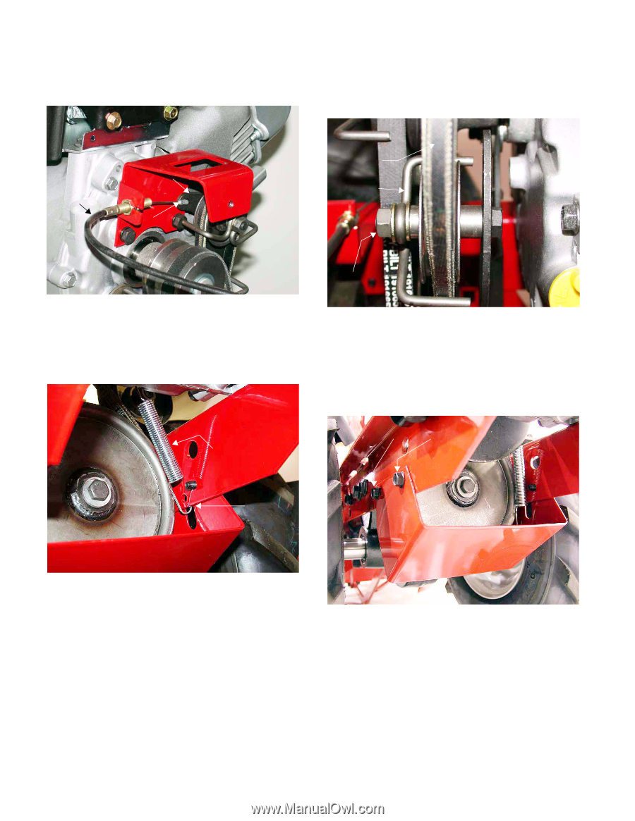
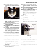
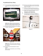
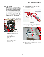
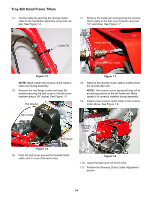
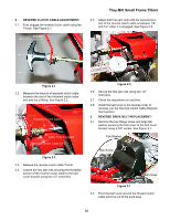
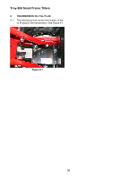
Troy-Bilt Small Frame Tillers 3.3. Remove the reverse clutch cable's Z-fitting from the reverse idler arm. See Figure 3.3. 3.4. Loosen the lock nut securing the reverse idler pulley belt guide in position using a 1/2" socket and wrench. See Figure 3.4. Reverse Clutch Cable Reverse Idler Arm Z-Fitting Reverse Drive Belt Belt Guide Figure 3.3 NOTE: The reverse return spring will drop off its anchoring position at the left frame rail. Make certain it is correctly installed during assembly. See the Image Below. Reverse Return Spring Lock Nut Figure 3.4 3.5. Remove the reverse drive belt from the reverse idler pulley. 3.6. Remove all four self-tapping screws securing the pulley/belt guard to the left and right engine brackets using a 3/8" socket and wrench. Self-Tapping Screws Anchor Position Reverse Return Spring Location Figure 3.6 NOTE: The wheel and tire assemblies can be move outward for extra clearance. 3.7. Remove the pulley/belt guard. 36
-
 1
1 -
2
-
3
-
4
-
5
-
6
-
7
-
8
-
9
-
10
-
11
-
12
-
13
-
14
-
15
-
16
-
17
-
18
-
19
-
20
-
21
-
22
-
23
-
24
-
25
-
26
-
27
-
28
-
29
-
30
-
31
-
32
-
33
-
34
-
 35
35 -
 36
36 -
 37
37 -
 38
38 -
 39
39 -
 40
40 -
 41
41 -
 42
42
 |
 |