Via ARTIGO A2000 Setup Guide
Via ARTIGO A2000 - VIA ARTiGO Barebone Storage Server Manual
 |
View all Via ARTIGO A2000 manuals
Add to My Manuals
Save this manual to your list of manuals |
Via ARTIGO A2000 manual content summary:
- Via ARTIGO A2000 | Setup Guide - Page 1
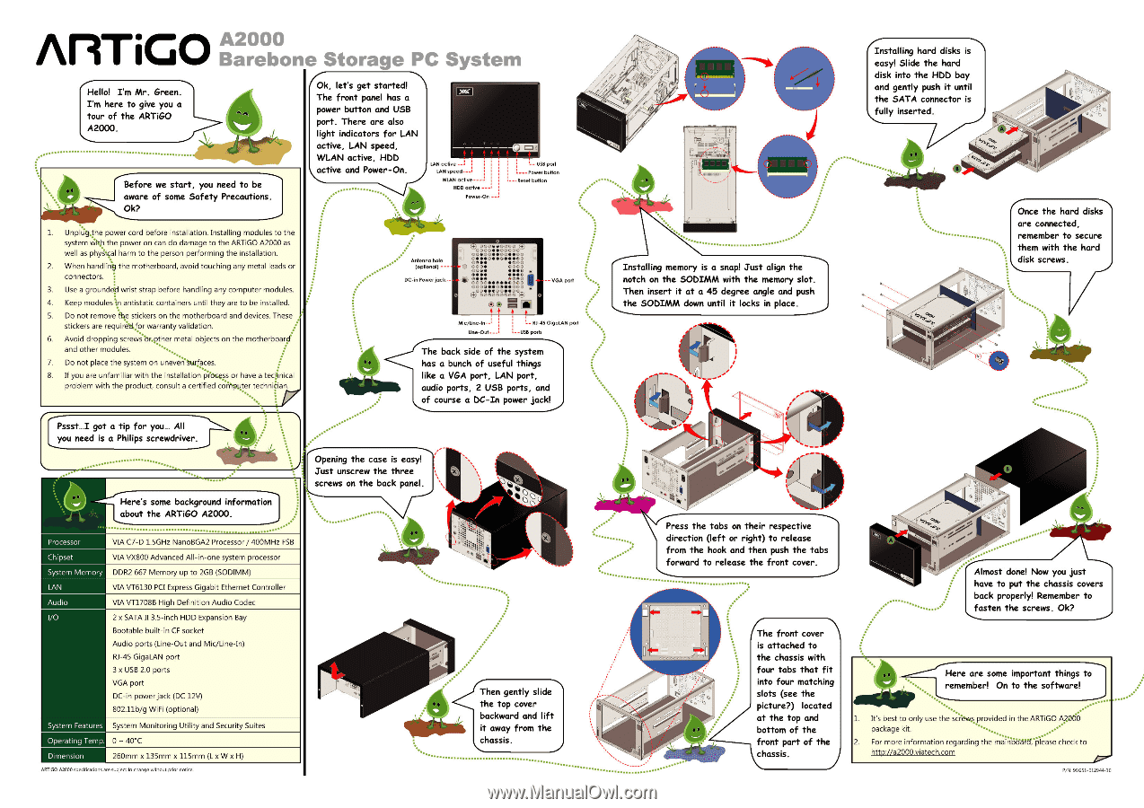
to be aware of some Safety Precautions. Ok? 1 UnplUq4he power cord before installation. Installing modules to the system Wirth the power on can do damage to the ARTiGO A2000 as well as physical harm to the person performing the installation. 2 When handlirig the motherboard, avoid touching any metal - Via ARTIGO A2000 | Setup Guide - Page 2
Installed hard disks main window shows real- time system monitoring data. The lower half shows information about • all attached hard disks. ... *The power on feature will be supported in a future update of the System Management Tool. Main window Auto-launch setting ARTiGO A2000
-
 1
1 -
 2
2
 |
 |
AirriGO
Hello!
I'm
Mr.
Green.
I'm
here
to
give
you
a
tour
of
the
ARTiGO
A2000.
Before
we
start,
you
need
to
be
aware
of
some
Safety
Precautions.
Ok?
1
UnplUq4he
power
cord
before
instal
lation.
Instal
ling
modules
to
the
system
Wirth
the
power
on
can
do
damage
to
the
ARTiGO
A2000
as
well
as
physical
harm
to
the
person
performing
the
instal
lation.
2
When
handlirig
the
motherboard,
avoid
touching
any
metal
leads
or
connectors.
3.
Use
a
grounded
wrist
strap
before
handling
any
computer
modules.
4.
Keep
moduleski
antistatic
containers
until
they
are
to
be
instal
led.
5.
Do
not
remove
fbe
stickers
on
the
motherboard
and
devices.
These
stickers
are
requiretLfor
warranty
validation.
6.
Avoid
dropping
screwsbr.pther
metal
objects
on
the
motherboard
and
other
modules.
7.
Do
not
place
the
system
on
uneverNorlffes.
8.
If
you
are
unfamiliar
with
the
installation
p
.
i'Ocess
or
have
a
technical
problem
with
the
product,
consult
a
certified
cornKiter
technician.
Pssst...I
got
a
tip
for
you...
All
you
need
is
a
Philips
screwdriver.
•.
O
•`
..•
-
....
„
Here's
some
background
information
about
the
ARTiGO
A2000.
...----'
Processor
VIA
C7
-D
1.5GHz
NanoBGA2
Processor
/
400MHz
FSB
Chipset
System
Memory
VIA
VX800
Advanced
Al
l
-in
-one
system
processor
DDR2
667
Memory
up
to
2GB
(SODIMM)
LAN
Audio
VIA
VT6130
PCI
Express
Gigabit
Ethernet
Control
ler
VIA
VT1708B
High
Definition
Audio
Codec
I/O
2
x
SATA
II
3.5
-inch
HDD
Expansion
Bay
Bootable
built-in
CF
socket
Audio
ports
(Line
-Out
and
Mic/Line-In)
RJ-45
GigaLAN
port
3
x
USB
2.0
ports
VGA
port
DC
-in
power
jack
(DC
12V)
802.11b/g
WiFi
(optional)
System
Features
Operating
Temp.
Dimension
System
Monitoring
Utility
and
Security
Suites
0
-
40°C
260mm
x
135mm
x
115mm
(L
x
W
x
H)
1
Ok,
let's
get
started!
The
front
panel
has
a
power
button
and
USB
port.
There
are
also
light
indicators
for
LAN
active,
LAN
speed,
WLAN
active,
WAD
active
and
Power
-On.
•
....
• •
........
. .
•
Antenna
hole
(optional)
DC
-in
Power
jack
•
LAN
active
LAN
speed—.
WLAN
active--
HDD
active
—
Power
-On
--
USB
porl
Power
button
---Reset
button
,4)
000eeocoo
,s-
0000••oC
O
O
O
-
C
•00••0011111100
C•••00•041,41141C0
ctl.••
•e)OO
0000
0000
0044/
•••6)
II•••
•••o
v•••
troerD•
•••0000
C000••010••000
,
OO••eriD••OO
00000
,
)000
(4
.)
® C
4'
ca
+
•
4
.
_
--
VGA
port
I
--
R1-45
GigaLAN
port
Line
-Out---
--USB
ports
The
back
side
of
the
system
has
a
bunch
of
useful
things
like
a
VGA
port,
LAN
port,
audio
ports,
2
USB
ports,
and
of
course
a
DC
-In
power
jack!
.•
Opening
the
case
is
easy!
Just
unscrew
the
three
screws
on
the
back
panel.
............
•
.........
•
••••••
........................
•
Then
gently
slide
the
top
cover
backward
and
lift
it
away
from
the
..................................................
//I'
'el
/17
.....
•
•
•
•
•
•
•
1
,
131
III
10111.4.1111.101111
,
111 I
o
...
***
.
.....
Installing
memory
is
a
snap!
Just
align
the
notch
on
the
SODIMM
with
the
memory
slot.
Then
insert
it
at
a
45
degree
angle
and
push
the
SODIMM
down
until
it
locks
in
place.
4
I
•'
•
Press
the
tabs
on
their
respective
direction
(left
or
right)
to
release
from
the
hook
and
then
push
the
tabs
forward
to
release
the
front
cover.
411•3
NO*.
4•.
cca
0.
.7
•
(The
front
cover
is
attached
to
the
chassis
with
four
tabs
that
fit
into
four
matching
slots
(see
the
picture?)
located
at
the
top
and
bottom
of
the
front
part
of
the
chassis.
Installing
hard
disks
is
easy!
Slide
the
hard
disk
into
the
HDD
bay
and
gently
push
it
until
the
SATA
connector
is
K
fc
...
illy
inserted.
.....
••
...........
•••
..................
`tea
,
(
Once
the
hard
disks
are
connected,
remember
to
secure
them
with
the
hard
l
disk
screws.
...........
Almost
done!
Now
you
just
have
to
put
the
chassis
covers
back
properly!
Remember
to
\...
tstep
the
screws.
Ok?
*
•
..•••
2.
For
more
information
regarding the
maintbAPtrplease
check
to
-----
Here
are
some
important
things
to--...,
t
.......
remember!
On
to
the
software!
_
.......
--'
....
.....
-
.
..
.......
1.
It's
best
to
only
use
the
screws
provided
in
the
ARTiGO
A000
.„•
*
package
kit.
..-
••
......
ARTiGO
A2000
specifications
are
subject
to
change
wthoi..t
prior
not
ce.
P/N:
99O51-012944-10