Via EPIA-ML8000AG User Manual
Via EPIA-ML8000AG - VIA Motherboard - Mini ITX Manual
 |
View all Via EPIA-ML8000AG manuals
Add to My Manuals
Save this manual to your list of manuals |
Via EPIA-ML8000AG manual content summary:
- Via EPIA-ML8000AG | User Manual - Page 1
User's Manual EPIA-ML Mini-ITX Mainboard Version 1.0 July 7, 2004 - Via EPIA-ML8000AG | User Manual - Page 2
or translated into any language, in any form or by any means, electronic, mechanical, magnetic,optical, chemical, manual or otherwise without the prior written permission of VIA Technologies Incorporated. Trademarks Windows CE™, Windows XP™, Windows 2000™, Windows ME™, Windows 98™ and plug and play - Via EPIA-ML8000AG | User Manual - Page 3
. This equipment generates, uses and can radiate radio frequency energy and, if not installed and used in accordance with the instruction manual, may cause harmful interference to radio communications. Operation of this equipment in a residential area is likely to cause harmful interference - Via EPIA-ML8000AG | User Manual - Page 4
1. Always read the safety instructions carefully. 2. Keep this User's Manual for future reference. 3. Keep this equipment away from . 11. If any of the following situations arises, get the equipment checked by a service personnel: • The power cord or plug is damaged • Liquid has penetrated into the - Via EPIA-ML8000AG | User Manual - Page 5
Box Contents • 1 x VIA Mainboard • 1 x Quick Installation Guide • 1 x ATA-33/66/100 IDE Ribbon Cable • 1 x Driver Utilities CD v - Via EPIA-ML8000AG | User Manual - Page 6
2-6 Back Panel Ports 2-7 Connectors 2-12 Jumpers 2-19 Slots 2-20 Chapter 3: BIOS Setup 3-1 Entering Setup 3-2 Control Keys 3-2 Gettings Help 3-3 The Main Menu 3-30 Save & Exit Setup 3-32 Exit Without Saving 3-33 Chapter 4: Driver Installation 4-1 Driver Utilities 4-2 CD Content 4-3 vi - Via EPIA-ML8000AG | User Manual - Page 7
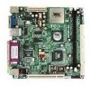
Chapter Specifications The ultra-compact and highly intergrated VIA EPIA-ML Mini-ITX Mainboard is the smallest form factor mainboard specification available today, developed by VIA Technologies, Inc. as part of the company's open industry-wide total connectivity initiative. The mainboard enables - Via EPIA-ML8000AG | User Manual - Page 8
C3 / EDEN EBGA Processor (on board) • Enhanced Ball Grid Array Package (EBGA) • Internal L1 128KB and L2 64KB cache memory Chipset • VIA CLE266 North Bridge • VT8235 South Bridge Graphics • Integrated UniChrome graphics with MPEG-2 accelerator Audio • VT1616 six channel AC'97 Codec • 3 Audio jacks - Via EPIA-ML8000AG | User Manual - Page 9
LAN port; 1 Serial port • 2 USB 2.0 ports; 1 VGA port • 3 Audio jacks: line-out, line-in and mic-in; can be switched to 6 channel output with Smart 5.1 BIOS • AwardBIOS with 2 / 4Mbit flash memory Form Factor • 17 cm X 17 cm Mini-ITX (4 layers) 1-3 - Via EPIA-ML8000AG | User Manual - Page 10
-In Middle: Line-Out Bottom: Microphone Back Panel PS2_MS ATXPWR CPU DIMM CPUFAN SYSFAN IDE1 FIR SMBUS COM2 CI F_AUDIO USB 3/4 CIR CMOS BATTERY CLEAR_CMOS BIOS Socket IDE2 CD_IN PCI1 RJ45 WOL FAN3 F_PANEL Parallel (LPT1) Line-In Line-Out Microphone PS2_KB VGA Out USB COM1 1-4 - Via EPIA-ML8000AG | User Manual - Page 11
Back Panel Ports Port Audio Jacks COM 1 LPT1 PS2-MS PS2-KB RJ45 USB 1-2 VGA Out Description Line-Out, Line-In, Microphone Serial port Parallel port PS2 mouse port PS2 keyboard port 10/100 NIC port Universal Serial Bus ports 1 - 2 VGA out port Slots Slot DIMM PCI Description Memory module slot - Via EPIA-ML8000AG | User Manual - Page 12
Chapter 1 Onboard Connectors and Jumpers Connecter/Jumper ATXPWR CD_IN CIR CLEAR_CMOS COM2 F_AUDIO F_PANEL Fans FIR SMBUS IDE 1-2 USB 3/4 WOL Description ATX power cable connector Onboard CD audio cable connector Consumer IR connector Jumper to reset CMOS settings to default Second serial port - Via EPIA-ML8000AG | User Manual - Page 13
Chapter Installation This chapter provides you with information about hardware setup procedures. While installing the mainboard, carefully hold the components and closely follow the installation procedures. Some components may be damaged if they are installed incorrectly. It is recommended to use - Via EPIA-ML8000AG | User Manual - Page 14
Chapter 2 CPU The VIA EPIA-ML Mini-ITX Mainboard includes an embedded VIA Eden Processor or VIA C3TM E-Series Processor. The CPUFAN (CPU fan) and SYSFAN (system fan) run on +12V and maintain system cooling. When connecting the wire to the connectors, - Via EPIA-ML8000AG | User Manual - Page 15
consumption and advanced thermal dissipation properties, the VIA Eden Processor features a fanless design. The VIA Eden Processor requires only a heatsink as shown. Installation Warning: This motherboard is not designed to support overclocking. Any attempt to operate beyond product specifications - Via EPIA-ML8000AG | User Manual - Page 16
Chapter 2 Memory Module Installation The VIA EPIA-ML Mini-ITX Mainboard provides one 184-pin DIMM slot for DDR266 SDRAM memory modules. DDR SDRAM Module Installation Procedures 1. Push the white retaining latches - Via EPIA-ML8000AG | User Manual - Page 17
Installation Available DDR SDRAM Configurations Refer to the table below for available DDR SDRAM configurations on the mainboard. Slot Memory Module DIMM (Bank 0 & 1) 64MB, 128MB, 256MB, 512MB, 1GB Maximum System Memory Supported Total Memory 64 MB - 1 GB 64 MB - 1 GB 2-5 - Via EPIA-ML8000AG | User Manual - Page 18
Chapter 2 Connecting the Power Supply The VIA EPIA-ML Mini-ITX Mainboard requires an ATX power supply to be connected. Before inserting the power supply connector, always make sure that all components are - Via EPIA-ML8000AG | User Manual - Page 19
Back Panel Ports The back panel has the following ports: PS2_MS RJ45 Parallel (LPT1) Installation Line-In Line-Out Microphone PS2_KB VGA Out USB COM1 Mouse Port: PS2_MS The mainboard provides a standard PS/2 mouse connector for attaching a PS/2 mouse. You can plug a PS/2 mouse directly - Via EPIA-ML8000AG | User Manual - Page 20
Chapter 2 VGA Out A DB-15 pin female connector that connects to a VGA monitor. USB Ports The mainboard provides 2 USB 2.0 ports. USB-compatible devices can be plugged directly into these ports. Pin Signal Description 1 VCC + 5V 2 - DATA Negative data channel 3 + DATA Positive data channel - Via EPIA-ML8000AG | User Manual - Page 21
Port: LPT1 The mainboard provides a 25-pin female connector for LPT (parallel port). A parallel port is a standard printer port that supports Enhanced Parallel Port (EPP) and Extended Capabilities Parallel Port (ECP) modes. 13 1 25 Pin Signal 1 STROBE 2 DATA0 3 DATA1 4 DATA2 5 DATA3 - Via EPIA-ML8000AG | User Manual - Page 22
Chapter 2 Serial Ports: COM1 The mainboard offers two 9-pin male Serial Port connectors COM1. You can attach a serial mouse or other serial devices directly to these ports. 1 5 69 9-Pin Serial Port Pin Signal 1 DCD 2 SIN 3 SOUT 4 DTR 5 GND 6 DSR 7 RTS 8 CTS 9 RI Description - Via EPIA-ML8000AG | User Manual - Page 23
to Smart 5.1 6-channel audio output. You can enable the function by clicking the "Vinyl Audio" icon on your desktop after installing the audio driver. After completing the previous settings, you need to connect your speakers to the audio jacks as shown below. PS2_MS RJ45 PS2_KB VGA Out USB - Via EPIA-ML8000AG | User Manual - Page 24
Chapter 2 Connectors Hard Disk Connectors: IDE1 & IDE2 The mainboard has a 32-bit Enhanced PCI IDE and Ultra DMA 33/66/100/ 133 controller that provides PIO mode 0~4, Bus Master, and Ultra DMA 33/ 66/100/133 functions. You can connect up to four hard disk drive, CDROM, LS-120 and other devices. - Via EPIA-ML8000AG | User Manual - Page 25
Installation Case Connectors: F_PANEL The F_PANEL connector block allows you to connect to the power switch, reset switch, power LED, HDD LED, SLED and the Speaker on the case. Pin Signal 1 PWR LED+ 3 PWR LED+ 5 PWR LED7 SPEAKER+ 9 NC 11 NC 13 SPEAKER15 NC Pin Signal 2 HDD LED+ 4 HDD LED6 PW_BN+ - Via EPIA-ML8000AG | User Manual - Page 26
IrDA Infrared Module Connector: IR This connector allows you to connect an IrDA Infrared module. You must configure the setting through the BIOS setup to activate the IR function. Pin Signal 1 VCC 2 IRRX1 3 IRRX 4 GND 5 IRTX FIR 1 5 Consumer Infrared Module, PS2 Header: CIR / EXT_KBMS - Via EPIA-ML8000AG | User Manual - Page 27
network card. Please note that the function of ACPI WOL may be disabled when users unplug the power cord or turn off the power button manually. WOL 2-15 - Via EPIA-ML8000AG | User Manual - Page 28
Chapter 2 COM2: Serial Port 2 COM2 is a pin header for second serial port. Pin Signal Description 1 DCD Data Carry Detect 2 SIN Serial In or Receive Data 3 SOUT Serial Out or Transmit Data 4 DTR Data Terminal Ready 5 GND Ground 6 DSR Data Set Ready 7 RTS Request To Send 8 CTS Clear To - Via EPIA-ML8000AG | User Manual - Page 29
CD Audio Connector: CD_IN This connector is for the CD-ROM audio connector. Installation CD_IN SM Bus Connector: SMBUS This is for connecting a System Management Bus device. Pin Signal 1 +3.3V 2 +3.3V 3 EL-ON 4 SMBCK 5 SMBDT 6 GND SMBUS 1 6 2-17 - Via EPIA-ML8000AG | User Manual - Page 30
Chapter 2 Front Audio Panel: F_AUDIO This connector allows you to connect a front audio panel to the mainboard. Only the line-out and microphone functions are available for use on the front panel. To connect the front audio cable, first remove the two red plastic jumpers. Pin Signal Pin Signal 1 - Via EPIA-ML8000AG | User Manual - Page 31
Jumpers Installation The mainboard provides jumpers for setting the mainboard's functions. This section will explain how to change settings for your mainboard's functions through the use of the jumpers. Clear CMOS: CLEAR_CMOS The onboard CMOS RAM stores system configuration data and has an - Via EPIA-ML8000AG | User Manual - Page 32
for the expansion card to make any necessary hardware or software settings for the expansion card, such as jumpers, switches or BIOS configuration. PCI Interrupt Request Routing The IRQ, abbreviation of interrupt request line and pronounced I-R-Q, are hardware lines over which devices can - Via EPIA-ML8000AG | User Manual - Page 33
. This chapter includes the following sections: Entering Setup Control Keys Gettings Help The Main Menu Standard CMOS Features Advanced BIOS Features Advanced Chipset Features Integrated Peripherals Power Management Setup PNP / PCI Configurations PC Health Status Frequency / Voltage Control Load - Via EPIA-ML8000AG | User Manual - Page 34
Chapter 3 Entering Setup Power on the computer and press Delete straight away to enter the BIOS setup menu. If you missed the BIOS setup entry point, you may restart the system and try again. Control Keys Keys Up Arrow Down Arrow Left Arrow Right Arrow Enter Escape Page - Via EPIA-ML8000AG | User Manual - Page 35
Setup Main Menu The main menu displays all BIOS setup categories. Use the control keys Up/Down Arrow Keys to enter the sub-menu. To return from the sub-menu press Esc. General Help: F1 The BIOS setup program provides a General Help screen. You can call up this screen from any menu/sub-menu by - Via EPIA-ML8000AG | User Manual - Page 36
F10 : Save & Exit Setup : Select Item Time, Date, Hard Disk Type... Standard CMOS Features Use this menu to set basic system configurations. Advanced BIOS Features Use this menu to set the advanced features available on your system. Advanced Chipset Features Use this menu to set chipset specific - Via EPIA-ML8000AG | User Manual - Page 37
and voltage control. Load Fail-Safe Defaults Use this menu option to load the BIOS default settings for minimal and stable system operations. Load Optimized Defaults Use this menu option to load BIOS default settings for optimal and high performance system operations. Set Supervisor Password Use - Via EPIA-ML8000AG | User Manual - Page 38
Chapter 3 Standard CMOS Features Date (mm:dd:yy) Time (hh:mm:ss) IDE Primary Master IDE Primary Slave IDE Secondary Master IDE Secondary Slave Phoenix - AwardBIOS CMOS Setup Utility Standard CMOS Features Tue, Apr 21 2004 20 : 20 : 20 [None] [QUANTUM FIREBALLP AS] [None] [None] Item Help Menu - Via EPIA-ML8000AG | User Manual - Page 39
BIOS Setup IDE Primary Master/Slave, Secondary Master/Slave Press Enter to enter the DMA Mode The name of this menu item will match the name of the menu. The settings are None, Auto, Manual. The settings are CHS, LBA, Large, Auto. The formatted size of the storage device. Number of cylinders. Number - Via EPIA-ML8000AG | User Manual - Page 40
the VIRUS warning feature for IDE Hard Disk Boot sector protection. If this function is enabled and someone attempt to write data into this area, BIOS will show a warning message on screen and alarm beep. : Move Enter: Select F5: Previous Values +/-/PU/PD: Value F10: Save F6: Fail-Safe Defaults - Via EPIA-ML8000AG | User Manual - Page 41
/Second/Third Boot Device Set the boot device sequence as BIOS attempts to load the disk operating system. The settings are: LS120 HDD-0 SCSI CD-ROM HDD-1 HDD-2 HDD-3 ZIP100 USB-FDD USB-ZIP USB-CDROM - Via EPIA-ML8000AG | User Manual - Page 42
end users try to run Setup. Display Full Screen Logo Show full screen logo during BIOS bootup process. Settings: Enabled and Disabled Show Summary Information Show the summary information during the BIOS boot process. Settings: Enabled and Disabled Display Small Logo Show small energy star logo - Via EPIA-ML8000AG | User Manual - Page 43
Advanced Chipset Features BIOS Setup The Advanced Chipset Features menu is used for optimizing the : 4MB, 8MB, 16MB, 32MB, 64MB, 128MB, and 256MB AGP Mode (Internal) This mainboard supports the AGP 4x interface. AGP 4x can transfer video data at 1066MB/s and is backward-compatible with AGP2x and - Via EPIA-ML8000AG | User Manual - Page 44
Chapter 3 CPU to PCI POST Write When Enabled, CPU can write up to four words of data to the PCI write buffer before CPU must wait for PCI bus cycle to finish. If Disabled, CPU must wait after each write cycle until PCI bus signals that it is ready to receive more data. Settings: Enabled and Disabled - Via EPIA-ML8000AG | User Manual - Page 45
AC97 Audio MC97 Audio VIA OnChip LAN [Enabled] [Enabled] [Enabled] [PCI Slot] [32M] [Auto] [Auto] [Enabled] Menu Level USB Keyboard Support Onboard LAN Boot ROM : PCI Slot and AGP Frame Buffer Size This setting instructs the BIOS to reserved the specified amount of memory for the internal video - Via EPIA-ML8000AG | User Manual - Page 46
controller cards to connect to a modem. Settings: Auto and Disabled VIA OnChip LAN This setting allows you to make VIA OnChip LAN enabled or disabled. Settings: Enabled and Disabled USB Keyboard Support Enable USB Keyboard Support for DOS and Windows. Settings: Enabled and Disabled Onboard Lan Boot - Via EPIA-ML8000AG | User Manual - Page 47
address and IRQ for the onboard serial port A/serial port B. Selecting Auto allows BIOS to automatically determine the correct base I/O port address. Settings: Port 1 2 allow the onboard parallel port to support both the ECP and EPP modes simultaneously. Settings: SPP, EPP, ECP, ECP + EPP 3-15 - Via EPIA-ML8000AG | User Manual - Page 48
Chapter 3 EPP Mode Select EPP (Enhanced Parallel Port) comes in two modes: 1.9 and 1.7. EPP 1.9 is the newer version of the protocol and is backwards compatible with most EPP devices. If your EPP device does not work with the EPP 1.9 setting, try changing the setting to EPP 1.7. Settings: EPP 1.9, - Via EPIA-ML8000AG | User Manual - Page 49
(POS)] [Disable] [Disable] [Suspend -> Off] [Instant-Off] [Auto] [Off] [Press Enter] [Press Enter] Item Help Menu Level This item allows you to select how the BIOS put the system in power saving mode. S1(POS): System in low power mode S3(STR): All components are powered off except memory. S1 & S3 - Via EPIA-ML8000AG | User Manual - Page 50
for more than four seconds. The power button functions as a normal power-on/off buttton. Run VGABIOS if S3 Resume Select whether to run VGA BIOS if resumed from S3 state. This is only necessary for older VGA drivers, select Auto if in doubt. Settings: Auto, Yes and No 3-18 - Via EPIA-ML8000AG | User Manual - Page 51
BIOS Setup Peripheral Activities Press Enter to enter the sub-menu and the following screen appears: Phoenix - AwardBIOS CMOS Setup Utility Peripherals Activities VGA Event LPT & - Via EPIA-ML8000AG | User Manual - Page 52
Chapter 3 PS2KB Wakeup from suspend Select which Hot-Key to wake-up the system from power saving mode. Settings: Disabled, Ctrl+F1, Ctrl+F2, Ctrl+F3, Ctrl+F4, Ctrl+F5, Ctrl+F6, Ctrl+F7, Ctrl+F8, Ctrl+F9, Ctrl+F10, Ctrl+F11, Ctrl+F12, Power, Wake and Any Key USB Resume Decide whether or not USB - Via EPIA-ML8000AG | User Manual - Page 53
BIOS Setup IRQs Activities Press Enter to enter the sub-menu and the following screen appears: Primary INTR IRQ3 (COM 2) IRQ4 (COM 1) to occur. After receiving the signal, when the operating system is ready, the system will interrupt itself and perform the service required by the IO device. 3-21 - Via EPIA-ML8000AG | User Manual - Page 54
Enter [Enabled] [Enabled] Item Help Menu Level Select Yes if you are using a Plug and Play capable operating system. Select No if you need the BIOS to configure non-boot devices. : Move Enter: Select F5: Previous Values +/-/PU/PD: Value F10: Save F6: Fail-Safe Defaults ESC: Exit F1: General F7 - Via EPIA-ML8000AG | User Manual - Page 55
configure all the boot and Plug and Play compatible devices. Choose Auto(ESCD) if unsure, the BIOS will automatically assign IRQ, DMA and memory base address fields. Settings: Auto (ESCD) and Manual Assign IRQ For VGA/USB Assign IRQ for VGA and USB devices. Settings: Disabled and Enabled - Via EPIA-ML8000AG | User Manual - Page 56
Chapter 3 IRQ Resources The items are adjustable only when Resources Controlled By is set to Manual. Press Enter and you will enter the sub-menu of the items. IRQ-3 assigned to IRQ-4 assigned to IRQ-5 assigned to IRQ-7 assigned to IRQ-9 - Via EPIA-ML8000AG | User Manual - Page 57
PC Health Status BIOS Setup This section shows the status of your CPU, fan, warning for overall system status. Current CPU Temp CPU Fan Speed System Fan Speed +5V - Via EPIA-ML8000AG | User Manual - Page 58
Exit F1: General F7: Optimized Defaults Help DRAM Clock The chipset supports synchronous and asynchronous mode between host clock and DRAM clock frequency. Settings: has a different performance rating than the original modules. Settings: Manual and By SPD SDRAM CAS Latency This item adjusts the - Via EPIA-ML8000AG | User Manual - Page 59
BIOS Setup Bank Interleave Set the interleave mode of the SDRAM interface. the SDRAM by masking the refresh time of each bank. This field is only available when DRAM Timing is set to Manual. Settings: Disabled, 2 Bank, 4 Bank Precharge to Active (Trp) This field controls the length of time it - Via EPIA-ML8000AG | User Manual - Page 60
you select Load-Fail Safe Defaults, a message as below appears: Phoenix - AwardBIOS CMOS Setup Utility Standard CMOS Features Advanced BIOS Features Advanced Chipset Features Integrated Peripherals Power Management Setup PnP / PCI Configurations PC Health Status Frequency / Voltage Control Load - Via EPIA-ML8000AG | User Manual - Page 61
Password PnP / PCI Configurations Load Optimized Defaults (SYa/Nv)e?&NExit Setup PC Health Status Exit Without Saving ESC : Quit F9 : Menu in BIOS F10 : Save & Exit Setup : Select Item Load Optimized Defaults Entering Y loads the default values that are factory settings for optimal and - Via EPIA-ML8000AG | User Manual - Page 62
Fail-Safe Defaults Load Optimized Defaults Set Supervisor Password Set User Password Save & Exit Setup Exit Without Saving ESC : Quit F9 : Menu in BIOS F10 : Save & Exit Setup : Select Item Change / Set / Disable Password Type the password, up to eight characters in length, and press Enter - Via EPIA-ML8000AG | User Manual - Page 63
. This would prevent unauthorized use of your computer. The setting to determine when the password prompt is required is the Security Option of the Advanced BIOS Features menu. If the Security Option is set to System, the password is required both at boot and at entry to Setup. If set to - Via EPIA-ML8000AG | User Manual - Page 64
Optimized Defaults Set Supervisor Password Set User Password SAVE to CMOS & EXIT (YS/aNv)e? & NExit Setup Exit Without Saving ESC : Quit F9 : Menu in BIOS F10 : Save & Exit Setup Save Data to CMOS : Select Item Entering Y will allow you to quit the Setup Utility and save the user setup changes - Via EPIA-ML8000AG | User Manual - Page 65
Load Optimized Defaults Set Supervisor Password Set User Password Quit Without Saving (Y/SNa)v?e &NExit Setup Exit Without Saving ESC : Quit F9 : Menu in BIOS F10 : Save & Exit Setup Abandon all Data : Select Item Entering Y will allow you to quit the Setup Utility without saving any changes - Via EPIA-ML8000AG | User Manual - Page 66
Chapter 3 3-34 - Via EPIA-ML8000AG | User Manual - Page 67
gives you brief descriptions of each mainboard drivers and applications. You must install VIA chipset drivers first before installing other drivers such as audio or VGA drivers. The applications will only function correctly if the necessary drivers are already installed. This chapter includes the - Via EPIA-ML8000AG | User Manual - Page 68
please contact your local dealer for the CD. Note: The driver utilities and software are updated from time to time. Please visit our website (http://www.viaembedded.com/) for the latest updated mainboard driver and utilities. Running the Driver Utilities CD To start using the CD, just simply insert - Via EPIA-ML8000AG | User Manual - Page 69
in this CD are: • VIA 4in1 Drivers: Contains VIA ATAPI Vendor Support Driver (enables the performance enhancing bus mastering functions on ATAcapable Hard Disk Drives and ensures IDE device compatibility), AGP VxD Driver (provides service routines to your VGA driver and interface directly to - Via EPIA-ML8000AG | User Manual - Page 70
Chapter 4 4-4
-
 1
1 -
 2
2 -
 3
3 -
 4
4 -
 5
5 -
 6
6 -
 7
7 -
8
-
9
-
10
-
11
-
12
-
13
-
14
-
15
-
16
-
17
-
18
-
19
-
20
-
21
-
22
-
23
-
24
-
25
-
26
-
27
-
28
-
29
-
30
-
31
-
32
-
33
-
34
-
35
-
36
-
37
-
38
-
39
-
40
-
41
-
42
-
43
-
44
-
45
-
46
-
47
-
48
-
49
-
50
-
51
-
52
-
53
-
54
-
55
-
56
-
57
-
58
-
59
-
60
-
61
-
62
-
63
-
64
-
65
-
66
-
67
-
68
-
69
-
70
 |
 |

User’s Manual
EPIA-ML
Mini-ITX Mainboard
Version 1.0
July
7
, 2004