Via EPIA-SP8000E User Manual
Via EPIA-SP8000E - VIA Motherboard - Mini ITX Manual
 |
View all Via EPIA-SP8000E manuals
Add to My Manuals
Save this manual to your list of manuals |
Via EPIA-SP8000E manual content summary:
- Via EPIA-SP8000E | User Manual - Page 1
User's Manual EPIA-SP Version 1.12 January 30, 2012 - Via EPIA-SP8000E | User Manual - Page 2
, chemical, manual or otherwise without the prior written permission of VIA Technologies, Incorporated. BIOS is a registered trademark of Phoenix Technologies Ltd. Disclaimer No license is granted, implied or otherwise, under any patent or patent rights of VIA Technologies. VIA Technologies - Via EPIA-SP8000E | User Manual - Page 3
and, if not installed and used in accordance with the instruction manual, may cause harmful interference to radio communications. Operation of user's authority to operate the equipment. Notice 2 Shielded interface cables and A.C. power cord, if any, must be used in order to comply with the emission - Via EPIA-SP8000E | User Manual - Page 4
1. Always read the safety instructions carefully. 2. Keep this User's Manual for future reference. 3. Keep this equipment If any of the following situations arises, get the equipment checked by a service personnel: • The power cord or plug is damaged • Liquid has penetrated into the equipment • - Via EPIA-SP8000E | User Manual - Page 5
BOX CONTENTS One VIA Mini-ITX mainboard One Quick Installation Guide One ATA-133/100 IDE ribbon cable One driver and utilities CD One IO bracket i - Via EPIA-SP8000E | User Manual - Page 6
the Power Supply 17 Back Panel Ports 19 Connectors 23 Jumpers 38 Slots 41 Chapter 3 43 BIOS Setup 43 Entering Setup 44 Control Keys 45 Navigating the BIOS Menus 46 Getting Help 47 Main Menu 48 Standard CMOS Features 50 IDE Drives 51 Advanced BIOS Features 52 Hard Disk Boot Priority - Via EPIA-SP8000E | User Manual - Page 7
Integrated Peripherals 59 Super IO Device 61 Power Management Setup 63 Peripheral Activities 65 IRQs Activities 68 PNP/PCI Configurations 69 IRQ / User Password 78 Save & Exit Setup 80 Exit Without Saving 81 Chapter 4 83 Driver Installation 83 Driver Utilities 84 CD Content 86 iii - Via EPIA-SP8000E | User Manual - Page 8
This page is intentionally left blank. iv - Via EPIA-SP8000E | User Manual - Page 9
developed by VIA Technologies, Inc. as part of the company's open industry-wide total connectivity initiative. The mainboard enables the creation of an exciting new generation of small, ergonomic, innovative and affordable embedded systems. Through a high level of integration, the Mini-ITX occupy 66 - Via EPIA-SP8000E | User Manual - Page 10
• Integrated UniChrome™ Pro AGP with MPEG-2 decoding Audio • VIA VT1617A 6-channel AC'97 Codec Memory • 1 x DDR 400 / 333 / 266 DIMM socket (up to 1 GB) Expansion Slot • 1 x PCI slot IDE • 2 x UltraDMA 133/100 connectors, with Direct DOM Support LAN • VIA VT6103 10/100 Base-T Ethernet PHY IEEE 1394 - Via EPIA-SP8000E | User Manual - Page 11
Fan and System Fan) • 1 x +12V power connector • 1 x SMBus connector • 1 x LVDS (function to be supported w/ an additional daughter card) • 1 x WP pin header BIOS • • Award BIOS with 4/8Mbit flash memory capacity ACPI2.0, SMBIOS2.1 and DMI2.2 Form Factor • Mini-ITX (6 layers) • 17 cm X 17 cm 3 - Via EPIA-SP8000E | User Manual - Page 12
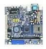
-Out Line-In Microphone ATXPWR KBMS +12V_PWR C3TM Processor CPUFAN SYSFAN DIMM1 SMBus CN400 LVDS VT8237R-series SPDIF_SEL1 COM2 FIR LPT USB 3/4 USB 5/6 USB 7/8 F_AUDIO CD_IN SPDIF 1394_1 BIOS Socket WP CLEAR_CMOS CMOS battery PCI Slot SATA_1 SATA_2 WOL VIP_2 J1 IDE1 IDE2 F_PANEL - Via EPIA-SP8000E | User Manual - Page 13
BACK PANEL LAYOUT PS/2 Mouse COM1 RJ45 RCA / SPDIF Specifications PS/2 Keyboard VGA Out USB S-Video Line-Out Line-In Microphone 5 - Via EPIA-SP8000E | User Manual - Page 14
Chapter 1 BACK PANEL PORTS Port Audio Jacks COM1 PS/2 Mouse PS/2 Keyboard RCA/SPDIF RJ45 USB VGA S-Video Description 3 Audio ports (line-out, line-in and mic-in) Serial port 1 PS/2 mouse port PS/2 keyboard port RCA port (SPDIF or TV out) RJ45 port USB 2.0 ports VGA port S-Video port SLOTS Port - Via EPIA-SP8000E | User Manual - Page 15
IDE 1-2 KBMS Header LPT LVDS SATA1 and 2 SMBus_Header SYSFAN USB 3-4/5-6/7-8 VIP_2 WOL Description 12V Power connector IEEE 1394 connector Power cable connector Onboard CD audio cable Reset CMOS settings IDE selector S/PDIF selector BIOS write protection setting Page 38-39 38, 40 38, 40 38, 40 7 - Via EPIA-SP8000E | User Manual - Page 16
Chapter 1 This page is intentionally left blank. 8 - Via EPIA-SP8000E | User Manual - Page 17
CHAPTER 2 Installation This chapter provides you with information about hardware installation procedures. It is recommended to use a grounded wrist strap before handling computer components. Electrostatic discharge (ESD) can damage some components. 9 - Via EPIA-SP8000E | User Manual - Page 18
Chapter 2 CPU The VIA C3 E-Series Processor The VIA EPIA-SP Mini-ITX mainboard includes an embedded VIA C3 or Eden Processor. The VIA C3 Processor provides ultra-low power consumption and advanced thermal dissipation properties. The VIA C3 Processor requires heatsink and a CPU fan to provide - Via EPIA-SP8000E | User Manual - Page 19
Eden Processor Providing ultra-low power consumption and advanced thermal dissipation properties, the VIA Eden Processor features a fanless design. The VIA Eden Processor requires only a heatsink as shown. Caution: This mainboard is not designed to support overclocking. Any attempt to operate beyond - Via EPIA-SP8000E | User Manual - Page 20
the Positive and should be connected to the +12V. The black wire is Ground and should always be connected to GND. The CPU system and power fan connectors have sensors to support fan monitoring except for +12V_CONN. 1 +12V_CONN 1 CPUFAN 1 SYSFAN C3TM Processor CN400 VT8237R 12 - Via EPIA-SP8000E | User Manual - Page 21
Installation +12V Power Connector This 12V power connector is used to provide additional +12V power to the rest of the system. Pin Signal 1 +12V 2 GND 1 +12V_CONN 13 - Via EPIA-SP8000E | User Manual - Page 22
2 MEMORY MODULE INSTALLATION The VIA EPIA-SP Mini-ITX mainboard provides one 184-pin DIMM slot for DDR400/333/266 SDRAM memory modules and supports the memory size up to 1GB. DDR SDRAM Module Installation Procedures • Locate the DIMM sockets in the motherboard. C3TM Processor DIMM1 14 VT8237R - Via EPIA-SP8000E | User Manual - Page 23
Installation • Unlock a DIMM socket by pressing the retaining clips outward. • Align a DIMM on the socket such that the notch on the DIMM matches the break on the socket. • Firmly insert the DIMM into the socket until the retaining clips snap back in place and the DIMM is properly seated. 15 - Via EPIA-SP8000E | User Manual - Page 24
Chapter 2 Available DDR SDRAM Configurations Refer to the table below for available DDR SDRAM configurations on the mainboard. Slot Module Size DIMM 64MB, 128MB, 256MB, 512MB, 1GB Maximum supported system memory Total 64MB-1GB 64MB-1GB 16 - Via EPIA-SP8000E | User Manual - Page 25
CONNECTING THE POWER SUPPLY The VIA EPIA-SP Mini-ITX mainboard supports a conventional ATX power supply for the power system. Before inserting the power supply connector, always make sure that all components are installed correctly to ensure that no damage will be caused. ATX 20-Pin Power Connector - Via EPIA-SP8000E | User Manual - Page 26
Chapter 2 ATX 20 Pin Power Connector Pin Signal Pin 1 +3.3V 11 2 +3.3V 12 3 GND 13 4 +5V 14 5 GND 15 6 +5V 16 7 GND 17 8 Power Good 18 9 +5V Standby 19 10 +12V 20 Signal +3.3V -12V GND Power Supply On GND GND GND NC +5V +5V 18 - Via EPIA-SP8000E | User Manual - Page 27
BACK PANEL PORTS The back panel has the following ports: PS/2 Mouse COM1 RJ45 RCA / SPDIF Installation PS/2 Keyboard VGA Out USB S-Video Line-Out Line-In Microphone Keyboard and Mouse The green 6-pin connector is for a PS/2 mouse. The purple connector is for a PS/2 keyboard. VGA Out The - Via EPIA-SP8000E | User Manual - Page 28
Chapter 2 RJ45 10/100 LAN Connector The mainboard provides a standard RJ-45 port. This port allows connection to a Local Area Network (LAN) through a network hub USB 2.0 ports 1and 2 These two 4-pin Universal Serial Bus (USB) ports are available for connecting USB 2.0 devices. S-Video port This port - Via EPIA-SP8000E | User Manual - Page 29
to Smart 5.1 6-channel audio output. You can enable the function by clicking the "Vinyl Audio" icon on your desktop after installing the audio driver. After completing the previous installation, connect the speakers to the 3-jack connectors on the back panel as shown. PS/2 Mouse COM1 RJ45 RCA - Via EPIA-SP8000E | User Manual - Page 30
Chapter 2 Shown below are the corresponding connections to setup the 6-channel system. Jack Line-out Line-in Microphone 2-channel Line-out Line-in Microphone 6-channel Front (Left/Right) Rear (Left/Right) Center/Sub-woofer 22 - Via EPIA-SP8000E | User Manual - Page 31
Installation CONNECTORS Hard Disk Connectors: IDE1 & IDE2 The mainboard has a 32-bit Enhanced IDE and Ultra DMA 133/100 controller that provides PIO mode 0~4, Bus Master, and Ultra DMA 133/100 functions. You can connect up to four hard disk drives, CD-ROM and other devices. The primary hard drive - Via EPIA-SP8000E | User Manual - Page 32
by the vendor for the jumper settings. Both IDE1 and IDE2 have a 20th pin included. The 20th pin was added to provide extra voltage to power 40-pin Disk-on Modules (DOM). See voltage selector: J1 on page 38 and 40. You must use IDE cables that do not block the - Via EPIA-SP8000E | User Manual - Page 33
CN400 VT8237R Installation Serial ATA Connectors: SATA1 and SATA2 These next generation connectors support the thin Serial ATA cables for primary internal storage devices. The current Serial ATA interface allows up to 150MB/s data transfer rate, faster than the - Via EPIA-SP8000E | User Manual - Page 34
Chapter 2 Case Connector: F_PANEL The F_PANEL pin header allows you to connect the power switch, reset switch, power LED, HDD LED and the case speaker. C3TM Processor CN400 VT8237R Case Connector: F_PANEL Pin Signal Pin 1 +5VDUAL 2 3 +5VDUAL 4 5 -PLED 6 7 +5V 8 9 NC 10 11 NC - Via EPIA-SP8000E | User Manual - Page 35
the HDD is still working. Connect the reset switch from the system case to this pin. Power LED (-PLED) The LED will light when the system is on. If the system is in S1 (POS Power On Suspend) or S3 (STR - Suspend To RAM) state, the LED will blink. HDD LED (HD_LED - Via EPIA-SP8000E | User Manual - Page 36
Chapter 2 Fast IrDA Infrared Module Connector: FIR This pin header is used to connect to an IrDA module. The BIOS settings must be configured to activate the IR function. Pin Signal 1 +5V 2 IRRX1 3 IRRX 4 GND 5 IRTX Description VCC FIR/SIR Data Receive SIR Data Receive - Via EPIA-SP8000E | User Manual - Page 37
be able to connect a 25-pin female external connector for LPT (parallel port). A parallel port is a standard printer port that supports Enhanced Parallel Port (EPP) and Extended Capabilities Parallel Port (ECP) modes. Pin Signal 1 STROBE 2 DATA0 3 DATA1 4 DATA2 5 DATA3 6 DATA4 7 DATA5 - Via EPIA-SP8000E | User Manual - Page 38
Chapter 2 USB Pin Connectors: USB 3-4, 5-6, and 7-8 The mainboard provides 3 front USB pin header connectors, allowing up to 6 additional USB2.0 ports up to maximum throughput of 480 Mbps. Connect each 2-port USB cable into each pin headers. These ports can be used to connect high-speed USB - Via EPIA-SP8000E | User Manual - Page 39
through the network card. Please note that the function of ACPI WOL may be disabled when users will unplug the power cord or turn off the power button manually. C3TM Processor CN400 1 COM2 1 CD_IN 1 1394 VT8237R 1 WOL Wake-On LAN connector: WOL Pin Signal 1 +5VDUAL 2 GND 3 WOL IN - Via EPIA-SP8000E | User Manual - Page 40
Chapter 2 Serial Port: COM 2 COM2 can be used to attach additional port for serial mouse or another serial device. Pin Signal 1 DCD 3 SOUT 5 GND 7 RTS 9 RI Pin Signal 2 SIN 4 DTR 6 DSR 8 CTS 10 Key 1 COM2 CD Audio Connector: CD_IN This connector allows you to receive stereo - Via EPIA-SP8000E | User Manual - Page 41
Installation System Management Bus Connector: SMBus The pin header allows you to connect SMBus (System Management Bus) devices. Devices communicate with an SMBus host and/or other SMBus devices using the SMBus interface. Pin Signal 1 SMBCK 2 SMBDT 3 GND 1 F_AUDIO VT8237R CN400 C3TM - Via EPIA-SP8000E | User Manual - Page 42
Audio Connector: F_AUDIO This is an interface for the VIA front panel audio cable that allow convenient connection and control microphone input 2 AGND Ground used by analog audio circuit 3 MIC_BIAS Microphone power 4 +5V AUDIO VCC used by analog audio circuit 5 LINE_OUT_R Right channel - Via EPIA-SP8000E | User Manual - Page 43
Installation Video Interface Port Pin Connector: VIP_2 This pin header allows you to use the capture function inside the North Bridge. Pin Signal 1 GND 3 CAPD7 5 CAPD6 7 GFPHS 9 CAPD1 11 GFPVS 13 SMBDT 15 SMBCK Pin Signal 2 CAPD0 4 CAPD4 6 CAPD5 8 CAPD2 10 CAPD3 12 - Via EPIA-SP8000E | User Manual - Page 44
CN400 VT8237R Chapter 2 LVDS Connector: This connector works as the interface to multi display devices. An additional daughter card is required for a certain display support. Daughter cards for LVDS and DVI are currently available respectively. C3TM Processor LVDS 36 - Via EPIA-SP8000E | User Manual - Page 45
LVDS Connector Pin Signal 1 GND 3 GFPCLK 5 GND 7 GFPD12 9 GFPD11 11 GFPD1 13 GND 15 GFPD6 17 GFPD7 GND 42 GFPVS 44 GFPHS 46 GFPDE 48 TVBSCK_R 50 TVBSDA_R Note: ENPVDD: Enable Panel VDD power ENVEE: Enable panel VEE power GFPD: Graphic Flat Panel Device signals. Installation 37 - Via EPIA-SP8000E | User Manual - Page 46
Chapter 2 JUMPERS The mainboard provides jumpers for setting some mainboard functions. This section will explain how to change the settings of the mainboard functions using the jumpers. 1 KBMS C3TM Processor CN400 1 RCA/SPDIF 1 J1 VT8237R 1 WP 1 CLEAR_CMOS 38 - Via EPIA-SP8000E | User Manual - Page 47
pins 2-3 for about 5~10 seconds, then move the cap back to pins 1-2. 4. Replace the battery. 5. Plug the power cord and turn ON the computer. 6. Hold down the key during the boot process and enter BIOS setup to re-enter data. Caution: Except when clearing the RTC RAM, never remove the cap on - Via EPIA-SP8000E | User Manual - Page 48
or 5V to the IDE device. Pin Signal 1 DOM_Power 2 +5V 3 DOM_Power 4 +3.3V 1 1 1-2: +5V (Default) 3-4: +3.3V BIOS Write Protection: WP This jumper allows you to protect from flashing the BIOS. BIOS 1 Write Protection setting: pin1 = /WP & /TBL, pin2 = GND, short 1-2 (default) WP 40 - Via EPIA-SP8000E | User Manual - Page 49
SLOTS Peripheral Component Interconnect: PCI The PCI slot allows you to insert PCI expansion card. When adding or removing expansion card, unplug first the power supply. Read the documentation for the expansion card if any changes to the system are necessary. C3TM Processor PCI Slot 41 VT8237R - Via EPIA-SP8000E | User Manual - Page 50
Chapter 2 PCI Interrupt Request Routing The IRQ (interrupt request line) are hardware lines over which devices can send interrupt signals to the microprocessor. The "PCI & LAN" IRQ pins are typically connected to the PCI bus INT A# ~ INT D# pins as follows: PCI Slot 1 IEEE1394 Order 1 INT B# INT - Via EPIA-SP8000E | User Manual - Page 51
CHAPTER 3 BIOS Setup This chapter gives a detailed explanation of the BIOS setup functions. 43 - Via EPIA-SP8000E | User Manual - Page 52
Chapter 3 ENTERING SETUP Power on the computer and press during the beginning of the boot sequence to enter the BIOS setup menu. If you missed the BIOS setup entry point, you may restart the system and try again. 44 - Via EPIA-SP8000E | User Manual - Page 53
BIOS Setup CONTROL KEYS Keys Up Arrow Down Arrow Left Arrow Right Arrow Enter Escape Page Up / + Page Down / F1 F5 F6 F7 F9 F10 Description - Via EPIA-SP8000E | User Manual - Page 54
The main menu displays all the BIOS setup categories. Use the control keys Up/Down arrow keys to select any item/sub-menu. Description of the selected/highlighted category is displayed at - Via EPIA-SP8000E | User Manual - Page 55
BIOS Setup GETTING HELP The BIOS setup program provides a "General Help" screen. You can display this screen from any menu/sub-menu by pressing . The help screen displays the keys for using and navigating the BIOS setup. Press to exit the help screen. 47 - Via EPIA-SP8000E | User Manual - Page 56
Chapter 3 MAIN MENU Phoenix - AwardBIOS CMOS Setup Utility Standard CMOS Features Advanced BIOS Features Advanced Chipset Features Integrated Peripherals Power Management Setup PnP / PCI Configurations PC Health Status Frequency / Voltage Control Load Fail-Safe Defaults Load Optimized Defaults - Via EPIA-SP8000E | User Manual - Page 57
and voltage control. Load Fail-Safe Defaults Use this menu option to load the BIOS default settings for minimal and stable system operations. Load Optimized Defaults Use this menu option to load BIOS default settings for optimal and high performance system operations. Set Supervisor Password Use - Via EPIA-SP8000E | User Manual - Page 58
Date The date format is [Day, Month Date Year] Time The time format is [Hour : Minute : Second] Halt On Sets the system's response to specific boot errors. Below is a table that details the possible settings. Setting All Errors No Errors All, But Keyboard Description System halts when any error is - Via EPIA-SP8000E | User Manual - Page 59
BIOS Setup IDE DRIVES IDE HDD Auto-Detection IDE Channel 0 Master Access Mode properly if you enter incorrect information in this category. Select "Auto" whenever possible. If you select "Manual", make sure the information is from your hard disk vendor or system manufacturer. Below is a table that - Via EPIA-SP8000E | User Manual - Page 60
Phoenix - AwardBIOS CMOS Setup Utility Advanced BIOS Features Hard Disk Boot Priority Virus Warning CPU Internal Cache Processor Number Feature Quick Power On Self Test First Boot Device Second Boot Device Third Boot Device Boot Other Device Boot Up NumLock Status Typematic Rate Setting Typematic - Via EPIA-SP8000E | User Manual - Page 61
devices if the system fails to boot from the "First/Second/Third Boot Device" list. Setting Enabled Disabled Description Enable alternate boot device No alternate boot device allowed Boot Up NumLock Status Set the NumLock status when the system is powered on. Setting On Off Description Forces - Via EPIA-SP8000E | User Manual - Page 62
prompt appears only when end users try to run BIOS Setup Password prompt appears every time when the computer is powered on and when end users try to run BIOS Setup Display Full Screen Logo Show full screen logo during BIOS boot up process. Settings: [Enabled, Disabled] Display Small Logo Show - Via EPIA-SP8000E | User Manual - Page 63
BIOS Setup HARD DISK BOOT PRIORITY Phoenix - AwardBIOS CMOS Setup Utility Hard Disk Boot Priority 1. Pri. Master : 2. Pri. Slave : 3. Sec. Master : 4. Sec. Slave : 5. USB-HDD0 : 6. USB-HDD1 : 7. USB-HDD2 : 8. Bootable Add-In Cards Item Help Menu Level Use < > or < > - Via EPIA-SP8000E | User Manual - Page 64
[CVBS] [Composite] [640x480] Item Help Menu Level If there are display cards on both AGP and PCI slots, configure this item for BIOS to select which one to boot : Move Enter: Select F5: Previous Values +/-/PU/PD: Value F10: Save F6: Fail-Safe Defaults ESC: Exit F1: General F7: Optimized Defaults - Via EPIA-SP8000E | User Manual - Page 65
Setup Frame Buffer Size This setting instructs the BIOS to reserved the specified amount of memory for the internal video controller. Settings: [16M, 32M, 64M, Disabled] Select Display Device This setting refers to the - Via EPIA-SP8000E | User Manual - Page 66
Chapter 3 VLink mode selection Phoenix - AwardBIOS CMOS Setup Utility CPU & PCI Bus Control [Mode 1] Item Help Menu Level : Move Enter: Select F5: Previous Values +/-/PU/PD: Value F10: Save F6: Fail-Safe Defaults ESC: Exit F1: General F7: Optimized Defaults Help 58 - Via EPIA-SP8000E | User Manual - Page 67
VIA OnChip LAN Onboard LAN Boot ROM [Enabled] [Enabled] [Enabled] [Enabled] [IDE Controller] [Auto] [Enabled] [Disabled] Menu Level Select IDE controller for install Win2000 / WinXP on your SATA Hard Driver controller contains an IDE interface with support for two IDE channels. Setting Enabled - Via EPIA-SP8000E | User Manual - Page 68
up to 150MB/sec. Setting IDE RAID Description Supports two SATA plus two PATA hard disk drives Only SATA supports RAID AC'97 Audio Auto allows the mainboard to controller to allow external controller VIA OnChip LAN Settings: [Enabled, Disabled] Onboard LAN Boot ROM Settings: [Enabled, Disabled - Via EPIA-SP8000E | User Manual - Page 69
Defaults Help Onboard Serial Port 1/2 Sets the base I/O port address and IRQ for the onboard serial ports A and B. Selecting "Auto" allows the BIOS to automatically determine the correct base I/O port address. Port 1 2 Settings Disabled Disabled 3F8 IRQ4 3F8 IRQ4 2F8 IRQ3 2F8 IRQ3 3E8 IRQ4 - Via EPIA-SP8000E | User Manual - Page 70
mode, choose EPP. By choosing ECP, the onboard parallel port will operate in ECP mode. Choosing ECP + EPP will allow the onboard parallel port to support both the ECP and EPP modes simultaneously. Settings: [SPP, EPP, ECP, ECP + EPP] EPP Mode Select EPP (Enhanced Parallel Port) comes in two modes - Via EPIA-SP8000E | User Manual - Page 71
] [Off] [Press Enter] [Press Enter] Item Help Menu Level This item allows you to select how the BIOS put the system in power saving mode. S1(POS): System in low power mode S3(STR): All components are powered off except memory. S1 & S3: Depends on OS to select S1 or S3 : Move Enter: Select - Via EPIA-SP8000E | User Manual - Page 72
button is pressed for more than four seconds Power button functions as a normal power-on/-off button Run VGABIOS if S3 Resume Select whether to run VGA BIOS if resuming from S3 state. This is only necessary for older VGA drivers. Settings: [Auto, Yes, No] AC Loss Auto restart The field defines - Via EPIA-SP8000E | User Manual - Page 73
BIOS Setup PERIPHERAL ACTIVITIES Phoenix - AwardBIOS CMOS Setup [Hot Key] [Disabled] [Disable] [Disabled] [Disabled] [Disabled] Item Help Menu Level Decide whether or not the power management unit should monitor VGA activities. RTC Alarm Resume Date (of Month) Resume Time (hh:mm:ss) [Disabled] - Via EPIA-SP8000E | User Manual - Page 74
: [Disabled, Ctrl+F1, Ctrl+F2, Ctrl+F3, Ctrl+F4, Ctrl+F5, Ctrl+F6, Ctrl+F7, Ctrl+F8, Ctrl+F9, Ctrl+F10, Ctrl+F11, Ctrl+F12, Power, Wake, Any Key] USB Resume Enables activity detected from USB devices to restore the system from a suspended state to an active state. Settings: [Disabled, Enabled - Via EPIA-SP8000E | User Manual - Page 75
BIOS Setup Wake On LAN Connector Enables any WOL signals from the modem to restore the system from a suspended state to an active state. Settings: [Disabled, Enabled] RTC Alarm Resume Sets a scheduled time and/or date to automatically power on the system. Settings: [Disabled, Enabled] Date (of Month - Via EPIA-SP8000E | User Manual - Page 76
Disabled] [Enabled] [Enabled] [Enabled] [Disabled] Item Help Menu Level If you choose Disabled, the power management unit will not monitor any IRQ activities. : Move Enter: Select F5: Previous Values +/-/PU/PD the system will interrupt itself and perform the service required by the IO device. 68 - Via EPIA-SP8000E | User Manual - Page 77
] [Enabled] Item Help Menu Level Select Yes if you are using a Plug and Play capable operating system. Select No if you need the BIOS to configure non-boot devices. : Move Enter: Select F5: Previous Values +/-/PU/PD: Value F10: Save F6: Fail-Safe Defaults ESC: Exit F1: General F7: Optimized - Via EPIA-SP8000E | User Manual - Page 78
to automatically configure all the Plug-and-Play compatible devices. Setting Auto(ESCD) Manual Description BIOS will automatically assign IRQ, DMA and memory base address fields Unlocks "IRQ Resources" for manual configuration Assign IRQ For VGA/USB Assign IRQ for VGA and USB devices. Settings - Via EPIA-SP8000E | User Manual - Page 79
BIOS Setup IRQ RESOURCES IRQ-3 assigned to IRQ-4 assigned to IRQ-5 assigned General F7: Optimized Defaults Help Note: The items are adjustable only when "Resources Controlled By" is set to "Manual." IRQ Resources list IRQ 3/4/5/7/9/10/11/12/14/15 for users to set each IRQ a type depending on the - Via EPIA-SP8000E | User Manual - Page 80
Chapter 3 PC HEALTH STATUS CPU Fan Speed System Fan Speed 5VSB +5V CPU Vcore 3.3V +12V Phoenix - AwardBIOS CMOS Setup Utility PC Health Status Item Help Menu Level : Move Enter: Select F5: Previous Values +/-/PU/PD: Value F10: Save F6: Fail-Safe Defaults ESC: Exit F1: General F7: Optimized - Via EPIA-SP8000E | User Manual - Page 81
BIOS Exit F1: General F7: Optimized Defaults Help DRAM Clock The chipset supports synchronous and asynchronous mode between host clock and DRAM clock frequency. Settings: a different performance rating than the original modules. Settings: [Manual, By SPD] SDRAM CAS Latency This item is for setting - Via EPIA-SP8000E | User Manual - Page 82
. This improves performance of the SDRAM by masking the refresh time of each bank. This field is only available when "DRAM Timing" is set to "Manual". Settings: [Disabled, 2 Bank, 4 Bank] Precharge to Active (Trp) This field is for setting the length of time it takes to precharge a row in the memory - Via EPIA-SP8000E | User Manual - Page 83
BIOS Setup ACT(0) to ACT(1) (TRRD) This field is only available when "DRAM Timing" is set to "Manual". Settings: [2T, 3T] Spread Spectrum When the mainboard's clock generator pulses, the extreme values (spikes) of the pulses creates EMI (Electromagnetic Interference). The Spread Spectrum - Via EPIA-SP8000E | User Manual - Page 84
Chapter 3 LOAD FAIL-SAFE DEFAULTS Phoenix - AwardBIOS CMOS Setup Utility Standard CMOS Features Advanced BIOS Features Advanced Chipset Features Integrated Peripherals Power Management Setup PnP / PCI Configurations PC Health Status Frequency / Voltage Control Load Fail-Safe Defaults Load - Via EPIA-SP8000E | User Manual - Page 85
CMOS Setup Utility Standard CMOS Features Frequency / Voltage Control Advanced BIOS Features Load Fail-Safe Defaults Advanced Chipset Features Load Optimized Defaults Integrated Peripherals Set Supervisor Password Power Management Setup Set User Password PnP / PCI Configurations Load - Via EPIA-SP8000E | User Manual - Page 86
Chapter 3 SET SUPERVISOR / USER PASSWORD Phoenix - AwardBIOS CMOS Setup Utility Standard CMOS Features Advanced BIOS Features Advanced Chipset Features Integrated Peripherals Power Management Setup PnP / PCI Configurations Enter Password: PC Health Status Frequency / Voltage Control Load Fail- - Via EPIA-SP8000E | User Manual - Page 87
BIOS Setup Additionally, when a password is enabled, the BIOS can be set to request the password each time the system is booted. This would prevent unauthorized use of the system. See "Security Option" in the "Advanced BIOS Features" section for more details. 79 - Via EPIA-SP8000E | User Manual - Page 88
Chapter 3 SAVE & EXIT SETUP Phoenix - AwardBIOS CMOS Setup Utility Standard CMOS Features Advanced BIOS Features Advanced Chipset Features Integrated Peripherals Power Management Setup PnP / PCI Configurations PC Health Status Frequency / Voltage Control Load Fail-Safe Defaults Load Optimized - Via EPIA-SP8000E | User Manual - Page 89
EXIT WITHOUT SAVING Phoenix - AwardBIOS CMOS Setup Utility Standard CMOS Features Advanced BIOS Features Advanced Chipset Features Integrated Peripherals Power Management Setup PnP / PCI Configurations PC Health Status Frequency / Voltage Control Load Fail-Safe Defaults Load Optimized Defaults - Via EPIA-SP8000E | User Manual - Page 90
Chapter 3 This page is intentionally left blank. 82 - Via EPIA-SP8000E | User Manual - Page 91
This chapter gives you brief descriptions of each mainboard driver and application. You must install the VIA chipset drivers first before installing other drivers such as audio or VGA drivers. The applications will only function correctly if the necessary drivers are already installed. 83 - Via EPIA-SP8000E | User Manual - Page 92
enhancing the performance of the mainboard. If the CD is missing from the retail box, please contact the local dealer for the CD. Note: The driver utilities and software are updated from time to time. The latest updated versions are available at http://www.viaembedded.com/ 84 - Via EPIA-SP8000E | User Manual - Page 93
the CD into the CD-ROM or DVD-ROM drive. The CD should run automatically after closing the CD-ROM or DVD-ROM drive. The driver utilities and software menu screen should then appear on the screen. If the CD does not run automatically, click on the "Start" button and select - Via EPIA-SP8000E | User Manual - Page 94
Power Management function). VIA Graphics Driver: Enhances the onboard VIA graphic chip. VIA Audio Driver: Enhances the onboard VIA audio chip. VIA USB 2.0 Driver: Enhances VIA USB 2.0 ports. VIA LAN Driver: Enhances the onboard VIA LAN chip. VIA FIR Driver: Support for FIR. VIA SATA Driver: Support
-
 1
1 -
 2
2 -
 3
3 -
 4
4 -
 5
5 -
 6
6 -
 7
7 -
8
-
9
-
10
-
11
-
12
-
13
-
14
-
15
-
16
-
17
-
18
-
19
-
20
-
21
-
22
-
23
-
24
-
25
-
26
-
27
-
28
-
29
-
30
-
31
-
32
-
33
-
34
-
35
-
36
-
37
-
38
-
39
-
40
-
41
-
42
-
43
-
44
-
45
-
46
-
47
-
48
-
49
-
50
-
51
-
52
-
53
-
54
-
55
-
56
-
57
-
58
-
59
-
60
-
61
-
62
-
63
-
64
-
65
-
66
-
67
-
68
-
69
-
70
-
71
-
72
-
73
-
74
-
75
-
76
-
77
-
78
-
79
-
80
-
81
-
82
-
83
-
84
-
85
-
86
-
87
-
88
-
89
-
90
-
91
-
92
-
93
-
94
 |
 |

User’s Manual
EPIA-SP
Version 1.12
January 30, 2012