Via EX10000EG User Manual - Page 25
Case Connector, F_PANEL, Power Switch PW_BN, Reset Switch RST_SW, Power LED -PLED_2, HDD LED HD_LED
 |
UPC - 825529003789
View all Via EX10000EG manuals
Add to My Manuals
Save this manual to your list of manuals |
Page 25 highlights
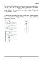
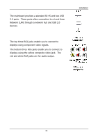
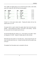
Installation Case Connector: F_PANEL The F_PANEL pin header allows you to connect the power switch, reset switch, power LED, sleep LED, HDD LED and the case speaker. F_PANEL Pin Signal 1 +5V 3 +5V 5 -PLED_2 7 +5V 9 NC 11 NC 13 SPEAK 15 Key Pin Signal 2 +5V 4 HD_LED 6 PW_BN 8 GND 10 RST_SW 12 GND 14 +5V 16 -SLEEP_LED 1 2 15 16 Power Switch (PW_BN) Connect to a 2-pin power button switch. Pressing this button will turn the system power on or off. Reset Switch (RST_SW) The reset switch is used to reboot the system rather than turning the power ON/OFF. Avoid rebooting the system, if the HDD is still working. Connect the reset switch from the system case to this pin. Power LED (-PLED_2) The LED will light when the system is on. If the system is in S1 (POS - Power On Suspend) or S3 (STR - Suspend To RAM) state, the LED will blink. HDD LED (HD_LED) HDD LED shows the activity of a hard disk drive. Avoid turning the power off when the HDD LED still has a lit. Connect the HDD LED from the system case to this pin. Speaker (SPEAK) The speaker from the system case is connected to this pin. 17
-
 1
1 -
2
-
3
-
4
-
5
-
6
-
7
-
8
-
9
-
10
-
11
-
12
-
13
-
14
-
15
-
16
-
17
-
18
-
19
-
 20
20 -
 21
21 -
 22
22 -
 23
23 -
 24
24 -
 25
25 -
 26
26 -
 27
27 -
 28
28 -
 29
29 -
 30
30 -
31
-
32
-
33
-
34
-
35
-
36
-
37
-
38
-
39
-
40
-
41
-
42
-
43
-
44
-
45
-
46
-
47
-
48
-
49
-
50
-
51
-
52
-
53
-
54
-
55
-
56
-
57
-
58
-
59
-
60
-
61
-
62
-
63
-
64
-
65
-
66
-
67
-
68
-
69
-
70
-
71
-
72
-
73
-
74
-
75
-
76
-
77
-
78
-
79
-
80
 |
 |
