ViewSonic PJ750 Service Manual - Page 27
suieiBwa, 5uuiM
 |
View all ViewSonic PJ750 manuals
Add to My Manuals
Save this manual to your list of manuals |
Page 27 highlights
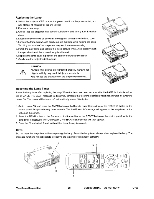
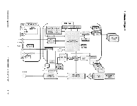
suieiBwa 5uuiM -6 U0REJ0dJ00 ORIOSMOIA Preparation for wiring of Power unit Wiring of Speaker (Caution) Cross CNPOW and the lead of To PWB ass'y Main Temperature sensor to keep distance between CNPOW and Primary source. (CNPOW) Temperature switch Temperature switch lead #ICN104 k,_CN102 2a' T201 Secondary - - source Power unit 0 -0 Primary source rs3 0 N., 0 Speaker (R) / / i f \\ I II // / ESPR: Upper view (Speaker) Position of rib of front bezel. Speaker (L) , ".„.• II 1 - 1' ji I I I \\ / 11 ESPL Position of rib of front bezel. CN101 Upper view (Power unit (circuit)) Speaker lead styling as shown chart, Use claw of upper case not put in rib when front bezel assembling. Route the CNBAR lead through the Ballast cover opening. CNBAR is made not be to leave over in the Ballast holder. (PAS* Clamp the CNBAR, CNPOW and CNTH. Power unit (Ballast) CN2 To PW1BBass'ylv1Wr15808 / To PWB ass'y Main E800 To PWB ass'y Main E302 CNBAR CNPOW E950 PWB ass'y sensor a _jjoN_1201,_4-H CN102 Temperature switch Lead of Power' • unit (Ballast) Power unit CN101 [ Speaker (R) ESPR ESPL PWB ass'y Main Upper view (Speaker) Upper case 1 Speaker (L) AdO0 ION oa -- 1VIINB0IANO3 Side view (Power unit (Circuit I Ballast)) Projection lens side
-
 1
1 -
2
-
3
-
4
-
5
-
6
-
7
-
8
-
9
-
10
-
11
-
12
-
13
-
14
-
15
-
16
-
17
-
18
-
19
-
20
-
21
-
 22
22 -
 23
23 -
 24
24 -
 25
25 -
 26
26 -
 27
27 -
 28
28 -
 29
29 -
 30
30 -
 31
31 -
 32
32 -
33
-
34
-
35
-
36
-
37
-
38
-
39
-
40
-
41
-
42
-
43
-
44
-
45
-
46
-
47
-
48
-
49
-
50
-
51
-
52
-
53
-
54
-
55
 |
 |
