ViewSonic PJL3211 PJL3211 User Guide (English) - Page 63
Connecting the cable, Communications setting
 |
UPC - 766907337617
View all ViewSonic PJL3211 manuals
Add to My Manuals
Save this manual to your list of manuals |
Page 63 highlights
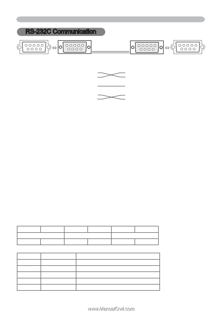
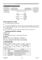
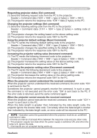
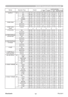
RS-232C Communication RS-232C Communication 1 23 45 67 8 9 1 23 45 67 8 9 CONTROL port RS-232C cable (Cross) of the projector - (1) (1) CD RD (2) (2) RD TD (3) (3) TD - (4) (4) DTR GND (5) - (6) (5) GND (6) DSR RTS (7) (7) RTS CTS (8) (8) DTS - (9) (9) RI RS-232C port of the PC Connecting the cable 1. Turn off the projector and the PC. 2. Connect the CONTROL port of the projector with a RS-232C port of the PC by a RS-232C cable (cross). Use the cable that fulfills the specification shown in the previous page. 3. Turn the PC on, and after the PC has started up turn the projector on. Communications setting 19200bps, 8N1 1. Protocol Consist of header (7 bytes) + command data (6 bytes). 2. Header BE + EF + 03 + 06 + 00 + CRC_low + CRC_high CRC_low : Lower byte of CRC flag for command data CRC_high : Upper byte of CRC flag for command data 3. Command data Command data chart byte_0 byte_1 Action low high byte_2 byte_3 Type low high byte_4 byte_5 Setting code low high Action (byte_0 - 1) Action Classification Content 1 SET Change setting to desired value. 2 GET Read projector internal setup value. 4 INCREMENT Increment setup value by 1. 5 DECREMENT Decrement setup value by 1. 6 EXECUTE Run a command. ViewSonic 58 PJL3211
-
 1
1 -
2
-
3
-
4
-
5
-
6
-
7
-
8
-
9
-
10
-
11
-
12
-
13
-
14
-
15
-
16
-
17
-
18
-
19
-
20
-
21
-
22
-
23
-
24
-
25
-
26
-
27
-
28
-
29
-
30
-
31
-
32
-
33
-
34
-
35
-
36
-
37
-
38
-
39
-
40
-
41
-
42
-
43
-
44
-
45
-
46
-
47
-
48
-
49
-
50
-
51
-
52
-
53
-
54
-
55
-
56
-
57
-
 58
58 -
 59
59 -
 60
60 -
 61
61 -
 62
62 -
 63
63 -
 64
64 -
 65
65 -
 66
66 -
 67
67 -
 68
68 -
69
-
70
-
71
-
72
-
73
-
74
-
75
-
76
-
77
-
78
 |
 |