Viking 15" Undercounter Wine Cellar Installation / Use and Care Instructions - Page 4
Caution
 |
View all Viking 15" Undercounter Wine Cellar manuals
Add to My Manuals
Save this manual to your list of manuals |
Page 4 highlights
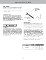
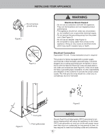
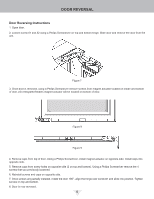
INSTALLING YOUR APPLIANCE Select Location The proper location will ensure peak performance of your appliance. We recommend a location where the unit will be out of direct sunlight and away from heat sources. To ensure your product performs to specifications, the recommended installation location temperature range is from 55 to 100°F (13 to 38°C). Front Grille, keep this area open. Cabinet Clearance Ventilation is required from the bottom front of the appliance. Keep this area open and clear of any obstructions. Adjacent cabinets and counter top can be installed around the appliance as long as the front grille remains unobstructed. All Professional models with articulated hinges are intended for built-in applications only. Front Leveling Legs Figure 2 Rear Leveling Legs ! CAUTION Front Grille Do not obstruct the front grille. The openings within the front grille allow air to flow through the condenser heat exchanger. Restrictions to this air flow will result in increased energy usage and loss of cooling capacity. For this reason it is important this area to not be obstructed and the grille openings kept clean. Viking Range, LLC does not recommend the use of a custom made grille as air flow may be restricted. (See Figure 2). Leveling Legs Adjustable legs at the front and rear corners of the appliance should be set so the unit is firmly positioned on the floor and level from side to side and front to back. The overall height of your appliance may be adjusted higher (by turning the leveling leg out, CCW) and lower (by turning the leveling leg in, CW) dimensions as shown in Table "A". To adjust the leveling legs, place the appliance on a solid surface and protect the floor beneath the legs to avoid scratching the floor. With the assistance of another person, lean the appliance back to access the front leveling legs. Raise or lower the legs to the required dimension by turning the legs. Repeat this process for the rear by tilting the appliance forward using caution. On a level surface check the appliance for levelness and adjust accordingly. The front grille screws may be loosened and the grille adjusted to the desired height. When adjustment is complete tighten the two front grille screws. (See Figure 5). Model VWUI5151 Door Style (G) Minimum Maximum Height Height 33 3⁄4" 34 3⁄4" (85.7 cm) (88.3 cm) Table A 4
-
 1
1 -
 2
2 -
 3
3 -
 4
4 -
 5
5 -
 6
6 -
 7
7 -
 8
8 -
 9
9 -
 10
10 -
11
-
12
-
13
-
14
-
15
-
16
 |
 |
