Viking VCWH 1200 CFM In-Line Ventilator Kit - Installation Instructions - Page 3
Connect Wiring To Dil1200 Inline Fan, Connect Wiring To The Range Hood Rough In Box
 |
View all Viking VCWH manuals
Add to My Manuals
Save this manual to your list of manuals |
Page 3 highlights
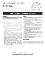
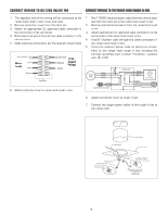
CONNECT WIRING TO DIL1200 INLINE FAN CONNECT WIRING TO THE RANGE HOOD ROUGH IN BOX 1. The opposite end of this wiring will be connected to the 1. Run 115VAC electrical power cable from the service panel range hood rough in box in the next step. and from the inline fan to the range hood rough in box. 2. Remove wiring box cover from the inline fan. 2. Remove appropriate knockouts from the range hood rough 3. Attach an appropriate UL approved cable connector to in box. the wiring hole in the wiring box. 3. Attach appropriate UL approved cable connectors to the 4. Bring electrical wiring through the cable connector in the wiring holes in the range hood rough in box. electrical box. 4. Feed 6" of power cable through the cable connectors in 5. Make electrical connections per the diagram shown below the range hood rough in box. 5. Using the diagram below make all electrical connec- tions to the range hood rough in box including the Cordset Assembly part number PV300207 supplied 115V with DIL1200. 6. Attach wiring box cover to range hood rough in box. 6. Attach wiring box cover to rough in box. 7. Connect the plugin power cables of the rough in box to the range hood. 3
-
 1
1 -
 2
2 -
 3
3 -
 4
4
 |
 |
