Viking VDD5300 VDVE900 - 900 CFM Exterior Power Ventilator - Installation Inst - Page 2
Prepare The Installation, Location, Prepare The Blower
 |
View all Viking VDD5300 manuals
Add to My Manuals
Save this manual to your list of manuals |
Page 2 highlights
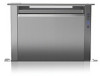
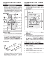
Roof Rafter Roof Rafter Wall Stud Wall Stud PREPARE THE INSTALLATION LOCATION ROOF INSTALLATIONS 1. Locate the blower on the rear slope of the roof. Place it in a location to minimize duct run. The location should be free of obstacles (T.V. leads, electrical lines, etc.). Bear in mind, if the blower top is level with the roof peak, it will not be seen from the street. Keep this approximate location in mind as you work from within the attic. Figure 1 20¾" 8½" 1 0 3 /8 " REMOVE SHINGLES Pilot Hole 11" dia. hole 20½" 1¼" dia. hole 9 1 /8 " 7¼" OUTSIDE - ROOF VIEW From inside the attic space: 2. Drill a PILOT HOLE up through the roof, 8½" from the inside edge of a ROOF RAFTER. From outside - on the roof: 3. Measure and mark the 20¾" x 20½" rectangle. Cut and remove only the shingles inside this rectangle. 4. Measure and mark the 11" DIAMETER HOLE and the 1¼" DIAMETER HOLE. Cut these holes all the way through the roof. PREPARE THE INSTALLATION LOCATION WALL INSTALLATIONS 1. Choose a position on the outside wall. Make sure that no wall studs, pipes or wires run through the opening area. Figure 3 24¾" 10¾" 1 2 7 /8 " 8½" Pilot Hole REMOVE SIDING 11" dia. hole 1¼" dia. hole 9 1 /8 " 28¼" 7¼" OUTSIDE - WALL VIEW From inside the wall: 2. Drill a PILOT HOLE through the wall, 8½" from the inside edge of a WALL STUD. From outside - on the wall: 3. Measure and mark the 25" x 29½" rectangle. Cut and remove only the siding inside this rectangle. 4. Measure and mark the 11" DIAMETER HOLE and the 1¼" DIAMETER HOLE. Cut these holes all the way through the wall. Figure 2 2" 24¾" 2" 6¾" 28¼" PREPARE THE BLOWER ALL INSTALLATIONS 1. Unpack the blower assembly. 2. Remove the cover and screws. 3. Remove and discard cardboard from blower wheel. 4. Remove the wiring box cover and screws. 5. For flat roof installations, build a curb that will mount the blower at a minimum pitch of 2/12. See Figure 5. Attach an appropriate U.L. approved cable connector in the hole at the rear of the wiring box. 2. Discharge end of the blower should be pointed away from prevailing winds. 2
-
 1
1 -
 2
2 -
 3
3 -
 4
4 -
 5
5 -
 6
6 -
 7
7 -
 8
8 -
9
-
10
-
11
-
12
 |
 |
