Waring CB15 Instruction Manual - Page 6
inside the housing so that
 |
View all Waring CB15 manuals
Add to My Manuals
Save this manual to your list of manuals |
Page 6 highlights
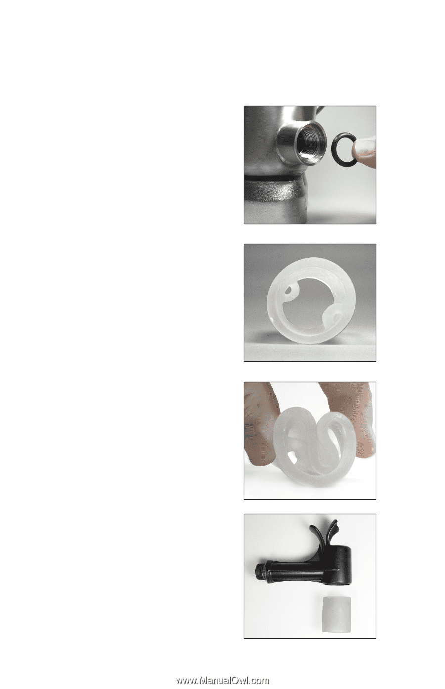
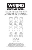
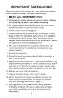
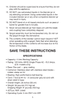
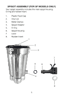
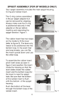
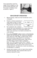
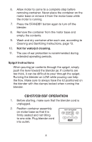
SPIGOT ASSEMBLY (FOR SF MODELS ONLY) Your spigot assembly includes the main spigot housing, O-ring and rubber insert. The O-ring comes assembled in the jar spigot adapter but can be removed for cleaning. Always make sure the O-ring is positioned securely in the adapter on the jar before inserting and operating the spigot function. Figure 1. fig. 1 The rubber insert has two loops on the inside to fit the lever (refer to figure 2). The lever only needs to be positioned into the bottom loop. In the event that one loop breaks, you can flip fig. 2 the insert upside down and use the other loop. To assemble the rubber insert pinch both sides as seen in figure 3 and position the insert inside the housing so that the lever slides inside the rubber insert and the bottom loop (for fig. 3 the lever) is near the spigot hole. Be sure that the bottom of the rubber insert is flush with the bottom of the spigot housing. Push the bottom of the lever through the bottom loop of the rubber insert. fig. 4 6
-
 1
1 -
 2
2 -
 3
3 -
 4
4 -
 5
5 -
 6
6 -
 7
7 -
 8
8 -
 9
9 -
 10
10 -
 11
11 -
 12
12 -
13
-
14
-
15
-
16
-
17
-
18
-
19
-
20
-
21
-
22
-
23
-
24
-
25
-
26
-
27
-
28
-
29
-
30
-
31
-
32
-
33
-
34
-
35
-
36
-
37
-
38
-
39
-
40
-
41
-
42
-
43
-
44
-
45
-
46
-
47
-
48
-
49
-
50
 |
 |