Weider 130 Bench English Manual - Page 10
Adjustment, Warning
 |
View all Weider 130 Bench manuals
Add to My Manuals
Save this manual to your list of manuals |
Page 10 highlights
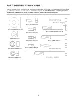
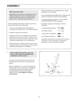
ADJUSTMENT This section explains how to adjust the weight bench. See EXERCISE GUIDELINES on page 11 for important information about how to get the most benefit from your exercise program. Also, refer to the accompanying exercise guide to see the correct form for several exercises. Make sure all parts are properly tightened each time you use the weight bench. Replace any worn parts immediately. The weight bench can be cleaned with a damp cloth and a mild, non-abrasive detergent; do not use solvents. ADJUSTING THE BACKREST The Backrest (7) can be used in a declined posi- 7 tion, a level position, or any of three inclined posi- tions. To adjust the Backrest, first remove the Locking Pin (21) from the Frame (1). Move the Backrest to the desired position, and reinsert the Locking Pin into the Frame and an adjustment hole in the Pivot Bracket (6). WARNING: Make sure that the Locking Pin (21) is fully inserted through the Frame (1) and the Pivot Bracket (6). 1 21 6 Adjustment Holes 10
-
 1
1 -
2
-
3
-
4
-
 5
5 -
 6
6 -
 7
7 -
 8
8 -
 9
9 -
 10
10 -
 11
11 -
 12
12 -
 13
13 -
 14
14 -
 15
15 -
16
 |
 |
