Weider 140w/weight English Manual - Page 8
drawing.
 |
View all Weider 140w/weight manuals
Add to My Manuals
Save this manual to your list of manuals |
Page 8 highlights
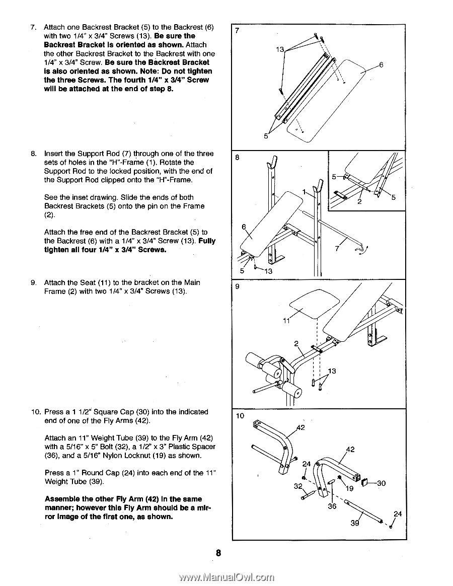
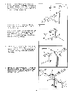
7. Attach one Backrest Bracket (5) to the Backrest (6) 7 with two 1/4" x 3/4" Screws (13). Be sure the Backrest Bracket is oriented as shown. Attach the other Backrest Bracket to the Backrest with one 13 1/4" x 3/4" Screw. Be sure the Backrest Bracket is also oriented as shown. Note: Do not tighten the three Screws. The fourth 1/4" x 3/4" Screw will be attached at the end of step 8. , . 5 8. Insert the Support Rod (7) through one of the three sets of holes in the "H"-Frame (1). Rotate the 8 Support Rod to the locked position, with the end of the Support Rod clipped onto the "H"-Frame. See the inset drawing. Slide the ends of both Backrest Brackets (5) onto the pin on the Frame (2). . 1 Attach the free end of the Backrest Bracket (5) to the Backrest (6) with a 1/4" x 3/4" Screw (13). Fully tighten all four 1/4" x 3/4" Screws. - NIA 5 13 9. Attach the Seat (11) to the bracket on the Main Frame (2) with two 1/4" x 3/4" Screws (13). 9 6 5 - 2 5 7 .." 10. Press a 1 1/2" Square Cap (30) into the indicated end of one of the Fly Arms (42). Attach an 11" Weight Tube (39) to the Fly Arm (42) with a 5/16" x 5" Bolt (32), a 1/2" x 3" Plastic Spacer (36), and a 5/16" Nylon Locknut (19) as shown. Press a 1" Round Cap (24) into each end of the 11" Weight Tube (39). Assemble the other Fly Arm (42) In the same manner; however this Fly Arm should be a mirror Image of the first one, as shown. 10 . i 11 ---/ 2 13 0 42 42 24 32 a C--30 19 36 24 39 8
-
 1
1 -
2
-
 3
3 -
 4
4 -
 5
5 -
 6
6 -
 7
7 -
 8
8 -
 9
9 -
 10
10 -
 11
11 -
 12
12 -
 13
13 -
14
-
15
-
16
 |
 |