Weider 265 English Manual - Page 15
Long U-Bracket 57 with a 1/4 Nylon Locknut
 |
View all Weider 265 manuals
Add to My Manuals
Save this manual to your list of manuals |
Page 15 highlights
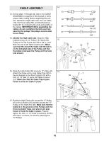
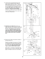
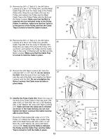
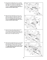
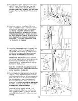
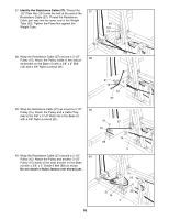
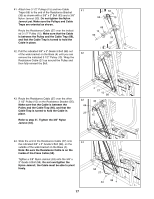
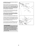
33. Route the Press Cable (58) between the indicat- 33 ed 3 1/2" Pulley (15) and the Cable Trap (66) attached to the Rear Upright (56). Make sure that the Cable Trap is turned to hold the Cable 56 15 in place. Properly tighten the 3/8" Nylon Locknut (21). 58 66 21 34. Attach the end of the Press Cable (58) to the Long "U"-Bracket (57) with a 1/4" Nylon Locknut (2) and a 1/4" Washer (10) (see the inset drawing). Do not completely tighten the Nylon Locknut; it should be threaded onto the end of the Cable until only two threads are showing above the Nylon Locknut, as shown in the inset drawing. Note: It may be necessary to remove the 3 1/2" Pulley (15) from the Long "U"-Bracket to do this step. 34 15 2 10 57 58 35. Attach the Resistance Bracket (35) inside of the upper bracket on the Front Upright (42) with a 3/8" x 2 1/4" Bolt (14) and a 3/8" Nylon Locknut (21). Do not overtighten the Nylon Locknut; the Bracket must be able to pivot easily. 35 88 See the inset drawing. Remove the indicated 3/8" x 1 1/4" Bolt (83) and 3/8" Nylon Jamnut (33) from the Resistance Handle (88). Attach the Cylinder (89) to the Resistance Handle with the Bolt and the Nylon Jamnut. Note: The Cylinder (89) should be turned so that the decal is on the same side as the knob on the Resistance Handle (88). 36. Pull out the knob on the Resistance Handle (88) as far as it will go. Slide the Resistance Handle onto the Resistance Bracket (35) and release the knob so that the pin on the knob is inserted into the upper adjustment hole in the Resistance Bracket. Tighten the four Nylon Jamnuts (not shown) on the Handle. Note: Do not overtighten the Nylon Jamnuts; the Handle must be able to slide across the Bracket easily. Attach the Cylinder (89) and two 5/8" x 7/8" Spacers (61) inside of the lower bracket on the Front Upright (42) with a 3/8" x 3 1/4" Bolt (68) and a 3/8" Nylon Locknut (21) (refer to the inset drawing). Knob 33 83 89 Decal 36 88 Knob 35 89 89 68 21 61 61 21 15 58 35 14 42 68 61 2 57 42 21
-
 1
1 -
2
-
3
-
4
-
5
-
6
-
7
-
8
-
9
-
 10
10 -
 11
11 -
 12
12 -
 13
13 -
 14
14 -
 15
15 -
 16
16 -
 17
17 -
 18
18 -
 19
19 -
 20
20 -
21
-
22
-
23
-
24
-
25
-
26
-
27
-
28
-
29
 |
 |
