Weider 355 English Manual - Page 9
Weider 355 Manual
 |
View all Weider 355 manuals
Add to My Manuals
Save this manual to your list of manuals |
Page 9 highlights
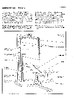
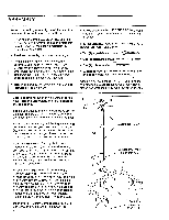
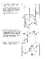
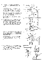
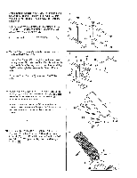
9. Route the Cable (51) around the indicated Pulley (24). Tighten the M10 Nylon Locknut (2) and the M10 x 120mm Bolt (not shown). Do not overtighten the Nylon Locknut. Be sure that both Cable Traps (23) are turned as shown and that the Cable and Pulleys move smoothly. 10. Wrap the Cable (51) around a Pulley (24). Attach the Pulley to the Top Frame (21) with an M10 x 89mm Bolt (9), an M10 Washer (10), and an M10 Nylon Locknut (2). Be sure that the cable stop is on the indicated side of the Pulley and that the Cable is between the Pulley and the welded post. 11. Press a 2" Square Inner Cap (46) into each end of the Stabilizer (33). Press a 2" Square Inner Cap (46) into the end of the Bench Base (43). Insert two M8 x 60mm Carriage Bolts (3) up through the Stabilizer (33). Slide the end of the Bench Base (43) onto the Carriage Bolts. Insert two M8 x 60mm Carriage Bolts (3) up through the Bench Base (43). 12. Slide the Bench Frame (49) onto the M8 x 60mm Carriage Bolts (3). Tighten an M8 Nylon Locknut (4) onto each Carriage Bolt. Press a 2" Square Inner Cap (46) into the Bench Frame (49). 9 23 4 2 O 51 0 . 0 0 0 10 51 21 0 2 0 0 9 24 0 Cable Stop 0 Welded 0 Post 11 .• 43 33 46 12 4 , 46 46 3 3 . 46 • 49 . , 4 , 2 3 3
-
 1
1 -
2
-
3
-
 4
4 -
 5
5 -
 6
6 -
 7
7 -
 8
8 -
 9
9 -
 10
10 -
 11
11 -
 12
12 -
 13
13 -
 14
14 -
15
-
16
-
17
-
18
-
19
-
20
 |
 |
