Weider 8512 English Manual
Weider 8512 Manual
 |
View all Weider 8512 manuals
Add to My Manuals
Save this manual to your list of manuals |
Weider 8512 manual content summary:
- Weider 8512 | English Manual - Page 1
HOT LINE: 1-800-225-0653 Mon.-Fri., 6 a.m.-6 p.m. MST ions' m this equipment:S: ave or future referep ns ru si g is.niartua PATENT PENDING 0 OO OO 0 USER'S MANUAL - Weider 8512 | English Manual - Page 2
attached to the center of this manual. Remove the PART IDENTIFICATION CHART before beginning assembly. LIMITED WARRANTY ICON Health & Fitness, Inc. (ICON), warrants this product to be free from defects in workmanship and material, under normal use and service conditions, for a period of ninety (90 - Weider 8512 | English Manual - Page 3
- Weider 8512 | English Manual - Page 4
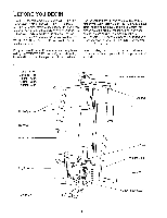
system, the WEIDER® 8512 will help you to achieve the specific results you want. Service Department toll-free WEIDER® 8512 (see the front cover of this manual). For your benefit, read this manual carefully before Before reading further, please review the drawing using the WEIDER® 8512 - Weider 8512 | English Manual - Page 5
in assembly, use the PART IDENTIFICATION CHART located in the center of this manual. Note: Some small parts may have been preattached for shipping. If a in the drawings. • Tighten all parts as you assemble them, unless instructed to do otherwise. THE FOLLOWING TOOLS (NOT INCLUDED) ARE REQUIRED FOR - Weider 8512 | English Manual - Page 6
) on the Weight Bumpers (19). Be sure that all of the Weights are turned so the pin grooves are on the same side and the "weider" logos are on top. 4 1 3 11 27 11 44 55 44 3 56 3 27 49 Crossbar 42 - Weider 8512 | English Manual - Page 7
6 Bolt (60), two 1/2" x 3/4" Spacers (61), and a 5/16" Nylon Locknut (3). Be sure that the Pulley Bracket (20) is in front of the right Weight Guide (62) as shown. 61 3 55 60 20 62 7. Press a 1" x 7/8" Plastic Bushing (75) onto each welded spacer on the Press Frame (17). Slide the Press - Weider 8512 | English Manual - Page 8
8. Press a 1 3/4" Square Inner Cap (44) into the top of a Press Arm (46). Press a 1" Round Inner Cap (49) into each end of the handle on the Press Arm. Attach the Press Arm to one side of the Press Frame (17) with two 5/16" x 2 1/2" Bolts (22) and two 5/16" Nylon Locknuts (3). 8 44 49 Assemble - Weider 8512 | English Manual - Page 9
11. During steps 11 through 25, refer to the CABLE DIAGRAM on page 20 of this manual to verify proper cable routing. Before beginning this section, identify the Long Cable (23) and the Short Cable (58) by comparing the lengths and ends - Weider 8512 | English Manual - Page 10
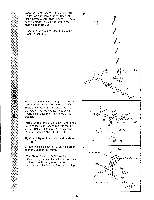
15. Route the Long Cable (23) around the "V"- 15 Pulley (6) on the Right Arm (48). Be sure ,, . that the Cable is in the groove of the "V"Pulley and that the Long Cable Trap (50) is turned to hold the Cable in place. Tighten the 3/8" x 2 1/2" Bolt (7) and the 3/8" Nylon Locknut (not shown). - Weider 8512 | English Manual - Page 11
19. Note: This assembly step shows how to 19 complete the assembly of several pre- attached parts. The 5/8" x 9/16" Spacer (73) has been preattached on the wrong side of the 3 1/2" Pulley (15) for shipping purposes. Remove the 3/8" Nylon Locknut (21), the Spacer, and the Pulley from the 3/8" x 3 - Weider 8512 | English Manual - Page 12
21. Route the Short Cable (58) around the 3 1/2" Pulley (15) attached to the lower hole in the Front Upright (42). See the inset drawing. Be sure that the Cable Trap (66) is turned to hold the Cable in place and that the Cable is routed around the Pulley as shown. Tighten the 3/8" Nylon Locknut (21) - Weider 8512 | English Manual - Page 13
24. Attach the end of the Short Cable (58) to the 24 Long "U"-Bracket (57) with a 1/4" Nylon Lock- nut (2) and a 1/4" Flat Washer (10). Do not completely tighten the Nylon Locknut. It should be threaded onto the end of the Cable only a couple of turns, as shown in the inset drawing. 0 57 58 - Weider 8512 | English Manual - Page 14
26. Attach the Backrest (41) to the Front Upright 26 (42) with two 1/4" x 2 1/2" Screws (43) and two 1/4" Rat Washers (10). 42 41 43 10 27. Press a 1 1/2" Square Inner Cap (32) into the Seat Frame (36). Insert the 1/4" x 2" Carriage Bolt (38) into the center hole in the Seat Plate (37). - Weider 8512 | English Manual - Page 15
29. Rest the Seat Frame (36) on the indicated pin 29 in the Front Upright (42). Attach the Seat Frame to the Front Upright with a 5/16" x 2 3/4" Carriage Bolt (14) and the Seat Knob (40). I I 14 Pin 42 40 36 w •ci) 30. Press 3/4" Round Inner Caps (34) into the 30 ends of both 12 1/2" Pad - Weider 8512 | English Manual - Page 16
If one of the cables does not move smoothly, find and correct the problem. IMPORTANT: If the cables are not properly installed, they may be damaged this manual for proper cable routing. If there is any slack in the 'cables, you will need to remove it by tightening the cables. See TROUBLE-SHOOTING - Weider 8512 | English Manual - Page 17
ADJUSTMENT The instructions below describe how each part of the home gym system can be adjusted. Refer to the exercise poster accompanying this manual to see how the home gym system should be set up for each exercise. IMPORTANT: When attaching the lat bar or nylon strap, make sure - Weider 8512 | English Manual - Page 18
ATTACHING AND REMOVING THE SEAT Set the bracket on the Seat Frame (36) onto the indicated pins on the Front Upright (42). Attach the Seat Frame to the Front Upright with the 5/16" x 2 3/4" Carriage Bolt (14) and the Seat Knob (40). For some exercises, the Seat (13) must be removed. First, be sure - Weider 8512 | English Manual - Page 19
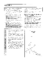
TROUBLE-SHOOTING AND MAINTENANCE Inspect and tighten all parts each time you use the home gym system. Replace any worn parts immediately. cable and re-install it. If the cables need to be replaced, see ORDERING REPLACEMENT PARTS on the back cover of this manual. 2 2315 66 57 21' 12 2 58 19 - Weider 8512 | English Manual - Page 20
CABLE DIAGRAM The cable diagram below shows the proper routing of the Short Cable (58) and the Long Cable (23). Use the diagram to be sure that the two cables and the cable traps have been assembled correctly. If the cables have not been correctly routed, the home gym system will not function
-
 1
1 -
 2
2 -
 3
3 -
 4
4 -
 5
5 -
 6
6 -
 7
7 -
8
-
9
-
10
-
11
-
12
-
13
-
14
-
15
-
16
-
17
-
18
-
19
-
20
 |
 |

Model
No.
WESY85120
Serial
No.
Write
the
serial
number
in
the
space
above
for
reference.
0
OO
O
0
II
Serial
Number
Decal
QUESTIONS?
As
a
manufacturer,
we
are
com-
mitted
to
providing
complete
customer
satisfaction.
If
you
have
questions,
or
find
that
there
are
missing
or
damaged
parts,
we
will
guarantee
you
complete
sat-
isfaction
through
direct
assis-
tance
from
our
factory.
TO
AVOID
UNNECESSARY
DELAYS,
PLEASE
CALL
DIRECT
TO
OUR
TOLL
-FREE
CUSTOMER
HOT
LINE.
The
trained
techni-
cians
on
our
customer
hot
line
will
provide
immediate
assis-
tance,
free
of
charge
to
you.
CUSTOMER
HOT
LINE:
1-800-225-0653
Mon.
—Fri.,
6
a.m.-6
p.m.
MST
ns
ru
ions'
m
si
g
this
equipment:
:
Save
is.niartua
or
future
referep
INE
DER
OO
0
OO
0
PATENT
PENDING
USER'S
MANUAL