Weider 8512 English Manual - Page 18
resistance
 |
View all Weider 8512 manuals
Add to My Manuals
Save this manual to your list of manuals |
Page 18 highlights
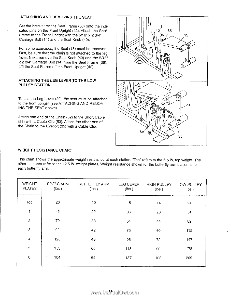
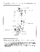
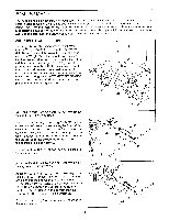
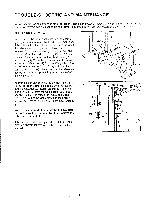
ATTACHING AND REMOVING THE SEAT Set the bracket on the Seat Frame (36) onto the indicated pins on the Front Upright (42). Attach the Seat Frame to the Front Upright with the 5/16" x 2 3/4" Carriage Bolt (14) and the Seat Knob (40). For some exercises, the Seat (13) must be removed. First, be sure that the chain is not attached to the leg lever. Next, remove the Seat Knob (40) and the 5/16" x 2 3/4" Carriage Bolt (14) from the Seat Frame (36). Lift the Seat Frame off the Front Upright (42). 40 36 13 42 0 141 ATTACHING THE LEG LEVER TO THE LOW PULLEY STATION To use the Leg Lever (29), the seat must be attached to the front upright (see ATTACHING AND REMOVING THE SEAT above). Attach one end of the Chain (52) to the Short Cable (58) with a Cable Clip (53). Attach the other end of the Chain to the Eyebolt (35) with a Cable Clip. 0 52 0 29 53 0 58 35 WEIGHT RESISTANCE CHART This chart shows the approximate weight resistance at each station. `Top" refers to the 6.5 lb. top weight. The other numbers refer to the 12.5 lb. weight plates. Weight resistance shown for the butterfly arm station is for each butterfly arm. WEIGHT PLATES PRESS ARM (lbs.) BUTTERFLY ARM (lbs.) LEG LEVER HIGH PULLEY LOW PULLEY (lbs.) (lbs.) (lbs.) Top 20 1 45 2 70 3 99 4 128 5 153 6 184 10 15 14 24 22 36 28 54 33 54 44 82 42 75 60 115 48 96 72 147 60 115 90 175 69 137 103 209 1R
-
 1
1 -
2
-
3
-
4
-
5
-
6
-
7
-
8
-
9
-
10
-
11
-
12
-
 13
13 -
 14
14 -
 15
15 -
 16
16 -
 17
17 -
 18
18 -
 19
19 -
 20
20
 |
 |