Weider Cts 2000 Club Series English Manual - Page 19
Pulley, Washer, Nylon, Metal, Bushing, Spacer, Welded, Bracket
 |
View all Weider Cts 2000 Club Series manuals
Add to My Manuals
Save this manual to your list of manuals |
Page 19 highlights
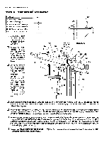
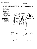
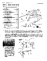
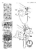
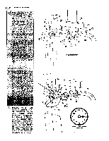
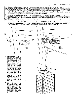
PAGE 23 WEIDER SPORTING GOODS STEP 8 CABLE ASSEMBLIES PART NAME 33 4 1/2" PULLEY 34 3 1/2" PULLEY 50 5116" FLAT WASHER 51 5/16" NYLON LOCK NUT . 52 5/16" X 2 1/4" HEX HEAD BOLT 54 5/16" X 2 112" HEX HEAD BOLT 55 5/16" X 1 1/2" HEX HEAD BOLT 57 5/16" X 3" HEX HEAD BOLT 59 5/16" X 3 3/4" HEX HEAD BOLT 60 5/16" X 31/4" HEX HEAD BOLT 61 5/16" X 31/2" HEX HEAD BOLT 62 3/8" FLAT WASHER 63 3/8" NYLON LOCK NUT 65 3/8" X 13/4" HEX HEAD BOLT 66 3/8" X 2" HEX HEAD BOLT 68 3/8" X 23/4" HEX HEAD BOLT 69 3/8" X 31/2" HEX HEAD BOLT 91 1/2"X 1" LONG METAL BUSHING 92 1/2" X 1/2" LONG SPACER 105 S-HOOK 119 5/16" THIN JAM NUT QTY 4 6 5 8 2 2 i 2 1 I 1 5 10 5 3 1 i I 2 2 2 32 12 68 a 6 92 33 2 62 0 63 24 STOPPER BALL Select the 133 1/2" LONG LAT CABLE (32) and insert the Cable up through the slot at the front of the TOP FRAME (12). Bring the Cable back along the Top Frame, through the Bracket on the top of the Frame and down through the access hole in the Frame. Pull the Cable completely through until the Stopper Ballis against the under side of the Frame. From underneath the TOP FRAME (12), fit a 4 1/2" PULLEY (A) (33) up into the slot in the front of the Top Frame and position the LAT CABLE (32) into the Pulley groove. Slide a 3/8" FLAT WASHER (62) and a 1/2" X 1/2" LONG METAL SPACER (92) onto a 3/8" X 2 3/4" HEX HEAD BOLT (68) and assemble the Bolt through the Top Frame and Pulley. Slide another 1/2" LONG SPACER (92) and 3/8" FLAT WASHER (62) over the Bolt and secure with a 3/8" NYLON LOCK NUT (63). u Fit a 3 1/27,PULLEY0) (34) under the • LAT CABLE- (32) vrAppitfpli2thetigiP e"Welded :Park' 6Ret WELDED PULLEY BRACKET 32 65 r • €,) u To install the LAT CABLE (32) into the 3 1/2" PULLEY (B) (34), it will be necessary to remove the Pulley by unfastening the 318" X 1 3/4" HEX HEAD BOLT (65) and 5/16" NYLON LOCK NUT (63). Remove the Pulley and assemble the Cable onto the Pulley and re-Install the Pulley In the Welded Pulley Bracket. B 34
-
 1
1 -
2
-
3
-
4
-
5
-
6
-
7
-
8
-
9
-
10
-
11
-
12
-
13
-
 14
14 -
 15
15 -
 16
16 -
 17
17 -
 18
18 -
 19
19 -
 20
20 -
 21
21 -
 22
22 -
 23
23 -
 24
24 -
25
-
26
 |
 |
