Weider Pro 265 Bench English Manual - Page 8
Attach the Backrest 13 to the Backrest Frames
 |
View all Weider Pro 265 Bench manuals
Add to My Manuals
Save this manual to your list of manuals |
Page 8 highlights
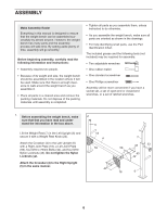
6. Attach the Backrest (13) to the Backrest Frames 6 (12) with four M6 x 40mm Bolts (49) and four M6 Washers (48). Do not tighten the Bolts yet. 13 12 12 48 48 48 49 7. Insert the Backrest Bracket (10) through the Bench Frame (1). Grease an M10 x 168mm Bolt (50). Attach the Backrest Frames (12) to the Bench Frame (1) with the Bolt and an M10 Nylon Locknut (43). Do not overtighten the Nylon Locknut; the Backrest Frames must pivot easily. Attach the Adjustment Pin (25) to the Bench Frame (1) with an M4 x 16mm Screw (45). Engage the Pin into the Bench Frame and the Backrest Bracket (10). Tighten the M6 x 40mm Bolts (49) and M6 Nylon Locknuts (51) used in steps 5 and 6. 49 7 12 10 43 1 25 50 45 8. Attach the Seat (14) to the Bench Frame (1) with 8 four M6 x 16mm Screws (39). 14 1 39 8
-
 1
1 -
2
-
 3
3 -
 4
4 -
 5
5 -
 6
6 -
 7
7 -
 8
8 -
 9
9 -
 10
10 -
 11
11 -
 12
12 -
 13
13 -
14
-
15
-
16
-
17
-
18
-
19
-
20
 |
 |
