Weider Pro 395 B Bench English Manual - Page 7
Attach a Weight Storage Tube 29 to the Left
 |
View all Weider Pro 395 B Bench manuals
Add to My Manuals
Save this manual to your list of manuals |
Page 7 highlights
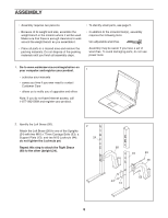
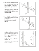
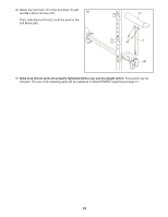
3. Orient the Crossbar (25) so that the warning decals (not shown) are on top. Attach one end of the Crossbar (25) to the Left Brace (26) with two M10 x 77mm Carriage Bolts (53), a Support Plate (13), and two M10 Locknuts (44); do not tighten the Locknuts yet. Repeat this step to attach the Crossbar (25) to the Right Brace (not shown). Then, tighten the M10 Locknuts (44) used in this step and in step 2. 3 53 25 53 26 13 44 4. Attach a Weight Storage Tube (29) to the Left Brace (26) with an M10 x 25mm Screw (49) and 4 an M10 Washer (41). 49 41 Repeat this step to attach the other Weight 60 Storage Tube (not shown) to the Right Brace (60). 29 5. Identify the Left Weight Rest (27). 5 Insert the Left Weight Rest (27) into the desired hole in the left Upright (24), and rotate it to the position shown in the inset drawing. Attach the Left Spotter (28) to the left Upright (24) in the same way. Repeat this step to attach the Right Weight Rest (58) and the Right Spotter (59) to the right Upright (24). 58 24 59 Make sure that both Weight Rests (27, 58) are at the same height and that both Spotters (28, 59) are at the same height. 26 24 27 28 7
-
 1
1 -
 2
2 -
 3
3 -
 4
4 -
 5
5 -
 6
6 -
 7
7 -
 8
8 -
 9
9 -
 10
10 -
 11
11 -
 12
12 -
13
-
14
-
15
-
16
-
17
-
18
-
19
-
20
 |
 |
