Weider Pro 4000 Uk Manual - Page 9
Arm Assembly
 |
View all Weider Pro 4000 manuals
Add to My Manuals
Save this manual to your list of manuals |
Page 9 highlights
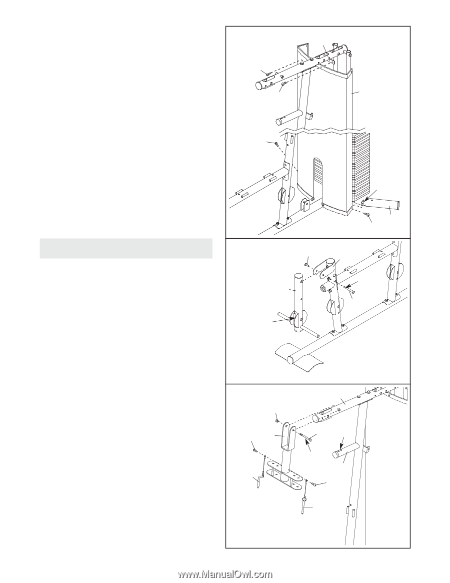
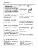
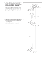
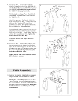
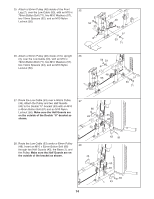
8. Attach the Shroud (17) to the Top Frame (4) 8 with two M4 x 16mm Screws (86). 4 Attach the Shroud (17) to the brackets on the Stabilizer (2) with two M4 x 16mm Screws (86). 86 Make sure the brackets are inside the Shroud. 17 Tighten the Nylon Locknuts (56, 58) used in 86 steps 2-6. 86 Bracket Arm Assembly 9. Grease the M10 x 70mm Bolt Set (73). Orient the Leg Lever (8) so that the welded support is on the side shown. Attach the Leg Lever to the Front Leg (7) with the Bolt Set. Do not overtighten the Bolt Set; the Leg Lever must pivot freely. 9 73 8 Welded Support 2 86 7 Grease 73 10. Grease an M10 x 90mm Button Bolt (67). Attach the Pivot Frame (5) to the Top Frame (4) with the Button Bolt and an M10 Nylon Locknut (56). Do not overtighten the Nylon Locknut; the Pivot Frame must pivot freely. Attach the two Arm Pins (40) to the Pivot Frame (5) with two M4 x 16mm Screws (86). Insert the Arm Pins into the two holes in the Upright (3). 10 56 86 5 40 4 67 Holes Grease 3 86 40 9
-
 1
1 -
2
-
3
-
 4
4 -
 5
5 -
 6
6 -
 7
7 -
 8
8 -
 9
9 -
 10
10 -
 11
11 -
 12
12 -
 13
13 -
 14
14 -
15
-
16
-
17
-
18
-
19
-
20
-
21
-
22
-
23
-
24
-
25
-
26
-
27
-
28
 |
 |