Weider Pro 875 English Manual - Page 7
Backrest to the Right and Left Backrest Frames
 |
View all Weider Pro 875 manuals
Add to My Manuals
Save this manual to your list of manuals |
Page 7 highlights
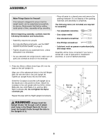
2. Press three 45mm Square Inner Caps (22) into the 2 Front Leg (1). Attach the Front Leg (1) to the Frame (2) with two M10 x 65mm Bolts (47), a Support Plate (16), and two M10 Nylon Locknuts (36). Do not tighten the Nylon Locknuts yet. 22 47 16 1 36 2 36 3. Attach the Frame (2) to the Crossbar (3) with two M10 x 81mm Bolts (35) and two M10 Nylon Locknuts (36). Do not tighten the Nylon Locknuts yet. 22 3 22 3 35 36 2 36 4. Press four 1" Square Inner Caps (23) into the 4 ends of the Right and Left Backrest Frames (7, 8). Press two 1" x 2" Inner Caps (24) into the adjustment tubes on the Backrest Frames. Orient the Backrest (10) as shown. Attach the Backrest to the Right and Left Backrest Frames (7, 8) with four M6 x 38mm Screws (39) and four M6 Washers (40). Do not tighten the Screws yet. 7 23 40 39 24 10 23 8 40 39 40 39 7
-
 1
1 -
 2
2 -
 3
3 -
 4
4 -
 5
5 -
 6
6 -
 7
7 -
 8
8 -
 9
9 -
 10
10 -
 11
11 -
 12
12 -
13
-
14
-
15
-
16
 |
 |
