Weider Pro 8900 English Manual
Weider Pro 8900 Manual
 |
View all Weider Pro 8900 manuals
Add to My Manuals
Save this manual to your list of manuals |
Weider Pro 8900 manual content summary:
- Weider Pro 8900 | English Manual - Page 1
. 831.14923.1 Serial No. Write the serial number in the space above for reference. Serial Number Decal WEIGHT SYSTEM EXERCISER Userʼs Manual • Assembly • Operation • Maintenance • Part List and Drawing Sears, Roebuck and Co. Hoffman Estates, IL 60179 CAUTION Read all precautions and instructions - Weider Pro 8900 | English Manual - Page 2
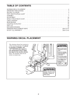
PLACEMENT 2 IMPORTANT PRECAUTIONS 3 BEFORE YOU BEGIN 4 PART IDENTIFICATION CHART 5 ASSEMBLY 7 ADJUSTMENT 34 WEIGHT RESISTANCE CHART 37 CABLE DIAGRAM 38 MAINTENANCE 39 EXERCISE GUIDELINES 40 PART LIST 43 EXPLODED DRAWING 45 ORDERING REPLACEMENT PARTS Back Cover 90-DAY FULL WARRANTY Back - Weider Pro 8900 | English Manual - Page 3
clothes while exercising; do not wear loose clothes that could become caught on the weight system. Always wear athletic shoes for foot protection. 11. Keep hands and feet away from moving parts. 3. Use the weight system only as described in this manual. 4. The weight system is intended for home use - Weider Pro 8900 | English Manual - Page 4
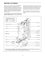
yourself with the parts that are labeled. Assembled Dimensions: Height: 6 ft. 11 in. (211 cm) Width: 4 ft. 1 in. (124 cm) Depth: 7 ft. 1 in. (216 cm) High Pulley Station Lat Bar Ab Station Backrest Right Side Seat Leg Lever Cable Clip Chain Foot Plate Burn Band Shroud Weight Weight Pin Butterfly - Weider Pro 8900 | English Manual - Page 5
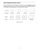
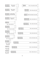
PART IDENTIFICATION CHART Refer to the drawings below to identify small parts used in assembly. The number in parentheses by each drawing is the key number of the part, from the PART LIST near the end of this manual. IMPORTANT: If you cannot find a part in the hardware kit, check to see if it has - Weider Pro 8900 | English Manual - Page 6
M10 x 57mm Bolt (93) M10 x 55mm Bolt (79) M10 x 50mm Button Bolt (76) M10 x 47mm Bolt (91) M6 x 45mm Bolt (85) M10 x 45mm Bolt (98) M10 x 43mm Bolt (65) M10 x 40mm Bolt (97) M10 x 20mm Screw (84) M6 x 16mm Screw (62) M4 x 12mm Bolt (107) M10 x 57mm Bolt Set (80) M10 x 63mm Bolt (89) M8 x 65mm - Weider Pro 8900 | English Manual - Page 7
read the following information and instructions: • Assembly requires two persons. • Because of its weight and size, assemble the weight system in the location where it will be used. Make sure that there is enough clearance to walk around the weight system. • Place all parts in a cleared area and - Weider Pro 8900 | English Manual - Page 8
3. Attach the U-stabilizer (3) to the Base (1) with two M10 x 68mm Bolts (66), two M10 Washers 3 (88), and two M10 Locknuts (74). 3 74 1 74 88 66 88 4. Orient the Upright (5) as shown. 4 Attach the Upright (5) to the Base (1) and the Side Stabilizers (2) with four M10 x 55mm Bolts (79), - Weider Pro 8900 | English Manual - Page 9
the Upright (5) with two M10 x 93mm Bolts (63), two M10 Washers (88), and two M10 Locknuts (74). Do not fully tighten the Locknuts yet. See steps 1, 4, 5, and 6. Tighten the M10 Locknuts (74). 6 74 74 8 10 74 88 74 5 88 63 66 88 9 - Weider Pro 8900 | English Manual - Page 10
DIAGRAM on page 38 to identify the cables as you assemble them. 8 Identify the Burn Cable (45). Identify the four Burn Pulleys (68), the three V-pulleys (not shown), and the twenty Pulleys (not shown). Route the threaded end of the Burn Cable (45) through the bracket on the Base (1) as shown - Weider Pro 8900 | English Manual - Page 11
10. Orient the Weight Guides (31) so that the indicated holes are closer to the floor. 10 Insert the Weight Guides (31) into the holes in the Base (1). Attach each Weight Guide with an M10 x 63mm Bolt (89) and an M10 Locknut (74). Holes 31 74 74 1 89 11 - Weider Pro 8900 | English Manual - Page 12
Cover (28) so that the notch is in the indicated location. 11 Slide the Bottom Cover (28) downward over the Weight Guides (31) and the Burn Cable (45). Make sure that the Burn Cable is routed as shown and is inserted into the notch in the Bottom Cover. 45 Notch 31 28 12. Make - Weider Pro 8900 | English Manual - Page 13
so that the pin hole is in the indicated location. Then, slide the Weight (30) onto the Weight Guides (31). Route the end of the Burn Cable (45) upward through the center of the Weight. Repeat these actions with the other eleven Weights. 31 45 30 Pin Hole 40 14. Orient the Top Frame (6) and the - Weider Pro 8900 | English Manual - Page 14
Weight 16 Guides (31) with two M10 x 43mm Bolts (65), two M10 Curved Washers (86), and two M10 Locknuts (74). See step 15. Tighten the M10 Locknuts (74). 17. Note: For clarity, the Top Cover (27) is not shown. 17 Route the Burn Cable (45) over two Burn Pulleys (68). Attach each Burn Pulley - Weider Pro 8900 | English Manual - Page 15
88 84 1 17 Grease 11 19. Identify the Butterfly Frame (7), the Left Butterfly Pulley Bracket (20), and the Left Butterfly Arm (15) and orient them as shown. (11), an Upper Butterfly Bushing (52), the Left Butterfly Pulley Bracket (20), and an M10 Locknut (74). Do not overtighten the Locknut; the - Weider Pro 8900 | English Manual - Page 16
(88), and two M10 Locknuts (74). Do not fully tighten the Locknuts yet. Insert a Ball Detention Assembly (96) into the Left and Right Butterfly Arms (15, 16). 63 6 88 16 96 96 15 Washers (88), and two M10 Locknuts (74). See step 20. Tighten the M10 Locknuts (74). 21 74 6 88 88 64 7 16 - Weider Pro 8900 | English Manual - Page 17
), and an M10 Locknut (74). 24. See drawing 24a. Route the Low Cable (43) under the Press Arm Spacer (42). 24a See drawing 24b. Attach a Pulley (69) to the bracket on the Base (1) over the Low Cable (43) with an M10 x 45mm Bolt (98) and an M10 Jam Nut (99). 10 - Weider Pro 8900 | English Manual - Page 18
69 74 1 71 91 27. Route the Low Cable (43) over a Pulley (69). 27 Attach the Pulley (69) and a Cable Trap (71) inside the Left and Right Press Arms (17, 18) with the M10 x 125mm Bolt (83) used in step 25, an M10 Washer (88), and an M10 Locknut (74). Make sure that - Weider Pro 8900 | English Manual - Page 19
). Make sure that the Cable Trap is oriented to hold the High Cable in the groove of the Pulley. 74 71 69 6 44 88 63 30. Route the High Cable (44) under a 30 V-pulley (67). Attach the V-pulley (67) and a Cable Trap (71) to the Upright (5) with an M10 x 57mm Bolt (93) and an M10 - Weider Pro 8900 | English Manual - Page 20
Locknut (74). Make sure that the Cable Trap is oriented to hold the High Cable in the groove of the Pulley. 32. Route the High Cable (44) around a Pulley (69). 32 Attach the Pulley (69) to the Upright (5) with an M10 x 43mm Bolt (65) and an M10 Locknut (74). 33. Route the High Cable - Weider Pro 8900 | English Manual - Page 21
. Note: For clarity, the Top Cover (27) is not shown in this step. 35 Slide the Top Cover (not shown) as far forward as possible. Route the High Cable (44) upward through the Top Frame (6), over a Pulley (69), and downward through the Top Frame as shown. Make sure to leave slack in the - Weider Pro 8900 | English Manual - Page 22
to leave slack in the High Cable (44) in the indicated location. 37. Insert a Pulley (69) into the loop of the High Cable (44) as shown. 37 Orient two Pulley Plates (70) as shown. Using the second hole in the Pulley Plates (70), attach the Pulley Plates to the Pulley (69) with an M10 x 43mm Bolt - Weider Pro 8900 | English Manual - Page 23
). Make sure that the Half Guards (72) are outside the bracket. 40. Route the Low Cable (43) over a Pulley (69). 40 Using the last hole in the Pulley Plates (70), attach the Pulley Plates to the Pulley (69) with an M10 x 43mm Bolt (65) and an M10 Locknut (74). 69 74 43 72 71 72 1 76 - Weider Pro 8900 | English Manual - Page 24
) is oriented to hold the Low Cable (43) in the groove of the Pulley (69). Make sure that the Half Guards (72) are outside the bracket. 43. Route the Low Cable (43) through the Upright (5) as shown. 43 Attach a V-pulley (67) inside the Upright (5) under the Low Cable (43) with an M10 x 65mm Bolt - Weider Pro 8900 | English Manual - Page 25
Tighten the lower end of the Burn Cable (45) completely into the Weight Selector (32). Insert the threaded end of the High Cable (44) through the upper end of the Burn Cable (45). Tighten the High Cable (44) at least five complete turns into the Weight Selector (32). Tighten the Nut (A) against - Weider Pro 8900 | English Manual - Page 26
). 46 30 41 47. Insert the Lock Pin (39) through a Weight Guide (31) and secure the Lock (38) into the Lock Pin. 47 31 38 39 48. Orient the Seat (24) and a Cushion Frame (9) as shown. 48 - Weider Pro 8900 | English Manual - Page 27
49. Insert the Cushion Frame (9) into the Seat Tube (8). 49 Tighten an Adjustment Knob (29) into the Seat Tube (8) and one of the holes in the Cushion Frame (9). Make sure that the Adjustment Knob is engaged in a hole. 9 8 29 50. Orient the Leg Lock Frame (12) as shown. Slide a Foam Pad (35) - Weider Pro 8900 | English Manual - Page 28
52. Orient the Backrest (25) and a Cushion Frame (9) as shown. Attach the Backrest (25) to the Cushion Frame (9) with four M6 x 16mm Screws (62). 52 25 9 62 62 53. Insert the Cushion Frame (9) into the Upright (5). 53 Tighten an Adjustment Knob (29) into the Upright (5) and one of the holes - Weider Pro 8900 | English Manual - Page 29
. Slide a Foam Pad (35) onto each side of the Leg (10). Then, press a Pad Cap (36) into the end of each Foam Pad. Repeat this step for the Leg Lever (13). 55 36 35 10 36 35 13 35 36 35 36 29 - Weider Pro 8900 | English Manual - Page 30
56. Note: For clarity, the Top Cover (27) is not shown in steps 56 to 58. 56 Identify the Center Shroud (33) and the Right and Left Side Shrouds (not shown). Orient the Center Shroud as shown. Insert - Weider Pro 8900 | English Manual - Page 31
58. Insert the Left Side Shroud (110) into the Bottom Cover (28). 58 6 Attach the top of the Left Side Shroud (110) to 34 the Top Frame (6) with an ST4.2 x 19mm Screw (90). Repeat this step to attach the Right Side Shroud (34). 90 110 28 31 - Weider Pro 8900 | English Manual - Page 32
59. Press the Top Cover (27) onto the Top Frame (6) as shown. 59 Orient the Burn Band (26) and the Burn Bracket (14) as shown. Insert the Burn Band into the Burn Bracket. Attach the Burn Bracket (14) and the Burn Band (26) to the Top Frame (6) with two M6 x 45mm Bolts (85) and two M6 Locknuts (87 - Weider Pro 8900 | English Manual - Page 33
use of the remaining parts will be explained in ADJUSTMENT, beginning on page 34. Before using the weight system, pull each cable a few times to make sure that the cables move smoothly around the pulleys. If one of the cables does not move smoothly, find and correct the problem. IMPORTANT: If the - Weider Pro 8900 | English Manual - Page 34
most benefit from your exercise program. Also, refer to the accompanying exercise guide to see the correct form for several exercises. Make sure that all parts are properly tightened each time the weight system is used. Replace any worn parts immediately. CHANGING THE WEIGHT SETTING To change the - Weider Pro 8900 | English Manual - Page 35
Cable (45). Then, insert the Burn Cable into the slot on the Burn Band. When the Burn Band (26) is not in use, attach the hook to the Top Frame (6). See the WEIGHT RESISTANCE CHART on page 37 to view the amount of resistance added by the burn band at each exercise station. 44 50 47 6 26 45 Slot - Weider Pro 8900 | English Manual - Page 36
low pulley station, rotate the Foot Plate upward. When you are not using the Foot Plate (4) as a footrest, rotate the Foot Plate downward so that it is flat on the floor. 4 LOCKING THE WEIGHT STACK To lock the weight stack after each workout, insert the Lock Pin (39) through one of the Weight Guides - Weider Pro 8900 | English Manual - Page 37
each station may vary due to differences in individual weights as well as friction between the cables, pulleys, and weight guides. WEIGHT RESISTANCE WITHOUT BURN BAND WEIGHT 1 2 3 4 5 6 7 8 9 10 11 12 AB STATION BUTTERFLY (lbs.) ARM (lbs.) 20 17 36 27 44 38 66 45 78 58 86 64 105 - Weider Pro 8900 | English Manual - Page 38
correctly. If the cables are not assembled correctly, the weight system will not function properly and damage may occur. Make sure that the cable traps do not touch or bind the cables. High Cable (44) Length: 168 in. (427 cm) 3 1 45 6 11 2 10 8 7 9 Burn Cable (45) Length: 133 in. (338 - Weider Pro 8900 | English Manual - Page 39
the Burn Cable (45). 44 A 45 32 Do not overtighten the cables. If the cables are overtightened, the top weight will be lifted off the weight stack. If a cable tends to slip off the pulleys often, it may have become twisted. Remove the cable and reinstall it. If the cables need to be replaced - Weider Pro 8900 | English Manual - Page 40
motivation, keep a record of each workout. Write the date, the exercises performed, the resistance used, and the numbers of sets and repetitions completed. Record your weight and key body measurements once a month. To achieve good results, make exercise a regular and enjoyable part of your life. 40 - Weider Pro 8900 | English Manual - Page 41
copies to schedule and record your strength and aerobic workouts. Scheduling and recording your workouts will help you to make exercise a regular and enjoyable part of your life. Strength Date: Exercise 1. Lbs. Sets Reps Exercise 6. Lbs. Sets Reps 2. 7. 3. 8. 4. 9. 5. 10. Aerobic Date - Weider Pro 8900 | English Manual - Page 42
NOTES 42 - Weider Pro 8900 | English Manual - Page 43
PART LIST Key No. Burn Band Top Cover Bottom Cover Adjustment Knob Weight Weight Guide Weight Selector Center Shroud Right Side Shroud Foam Pad Pad Cap Roll Pin Lock Lock Pin Bumper Weight Pin Press Arm Spacer Low Cable High Cable Burn Cable Model No. 831.14923 pulley Burn Pulley Pulley Pulley Plate - Weider Pro 8900 | English Manual - Page 44
Shroud Userʼs Manual Exercise Guide Grease Packet Assembly Tool Note: Specifications are subject to change without notice. For information about ordering replacement parts, see the back cover of this manual. If a part is missing, please call 1-877-992-5999. *These parts are not illustrated. 44 - Weider Pro 8900 | English Manual - Page 45
EXPLODED DRAWING A Model No. 831.14923.1 R0812A 104 103 47 48 74 63 74 86 74 27 86 88 6 88 87 87 65 102 14 46 53 52 103 21 104 - Weider Pro 8900 | English Manual - Page 46
EXPLODED DRAWING B 36 Model No. 831.14923.1 R0812A 90 36 35 34 36 31 90 53 19 55 36 35 105 74 35 53 54 18 55 55 84 57 88 42 - Weider Pro 8900 | English Manual - Page 47
EXPLODED DRAWING C Model No. 831.14923.1 R0812A 74 95 74 73 88 74 71 88 69 69 88 63 74 73 69 73 88 88 93 71 75 88 69 67 74 74 69 71 63 95 66 69 71 67 71 69 93 74 65 65 69 71 69 91 91 70 69 65 70 44 - Weider Pro 8900 | English Manual - Page 48
Get it fixed, at your home or ours! Your Home For repair-in your home-of all major brand appliances, lawn and garden equipment, or heating and cooling systems, no matter who made it, no matter who sold it! For the replacement parts, accessories, and user's manuals that you need to do-it-yourself.
-
 1
1 -
 2
2 -
 3
3 -
 4
4 -
 5
5 -
 6
6 -
 7
7 -
8
-
9
-
10
-
11
-
12
-
13
-
14
-
15
-
16
-
17
-
18
-
19
-
20
-
21
-
22
-
23
-
24
-
25
-
26
-
27
-
28
-
29
-
30
-
31
-
32
-
33
-
34
-
35
-
36
-
37
-
38
-
39
-
40
-
41
-
42
-
43
-
44
-
45
-
46
-
47
-
48
 |
 |
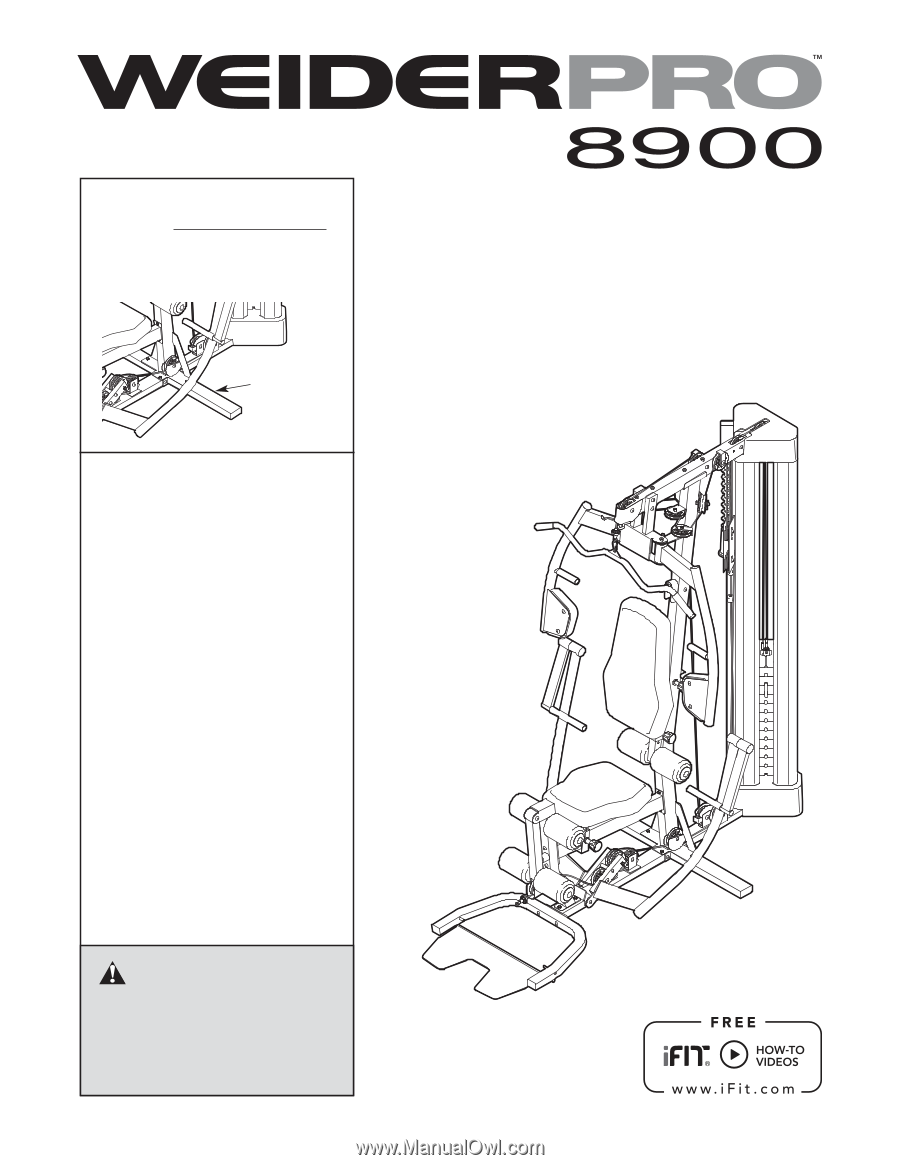
WEIGHT SYSTEM EXERCISER
Userʼs Manual
CAUTION
Read all precautions and instruc-
tions in this manual before using
this equipment. Keep this manual
for future reference.
Model No. 831.14923.1
Serial No.
Write the serial number in the
space above for reference.
• Assembly
• Operation
• Maintenance
• Part List and Drawing
Sears, Roebuck and Co.
Hoffman Estates, IL 60179
Serial Number
Decal