Weider Pro 9350 English Manual
Weider Pro 9350 Manual
 |
View all Weider Pro 9350 manuals
Add to My Manuals
Save this manual to your list of manuals |
Weider Pro 9350 manual content summary:
- Weider Pro 9350 | English Manual - Page 1
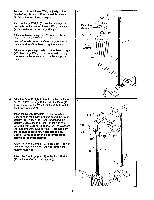
t$• PROFESSIONAL QUALITY FITNESS SYSTEM Model No. WG93500 Serial No. OWNER'S MANUAL Serial Number Decal (Under Seat) QUESTIONS? As a manufacturer, we ., 6 a.m.-6 p.m. MST 0 CAUTION! Read all safety precautions and instructions in this owner's manual before using this equipment. Save this owner - Weider Pro 9350 | English Manual - Page 2
BEGIN ASSEMBLY ADJUSTMENT TROUBLE-SHOOTING AND MAINTENANCE hard drive system. 1. Read all instructions in this owner's manual and in the accompanying literature before using persons with pre-existing health problems. Read all Instructions before using. WEIDER assumes no responsibility for personal - Weider Pro 9350 | English Manual - Page 3
achieve the specific results you want. For your safety and benefit, read this manual carefully before using the WEIDER 9350 Hard Drive System. it you nave additional questions, please cal' our Customer Service Department toil-tree ar 1-800-22o-U6b3 Monday through Friday, 6 a.m. until 6 p.m. Mountain - Weider Pro 9350 | English Manual - Page 4
Tighten all nuts and bolts as you attach them, unless instructed to do otherwise. For help identifying the small parts used in assembly, refer to the PART IDENTIFICATION CHART accompanying this owner's manual. THE FOLLOWING TOOLS (NOT INCLUDED) ARE REQUIRED FOR ASSEMBLY: two - Weider Pro 9350 | English Manual - Page 5
3. Turn each of the thirteen Weights (107) so the "weider" logo is on top. Press a Weight Sleeve (117) into the top of each Weight. Turn the Large Weight (61) so the deepest pin groove is - Weider Pro 9350 | English Manual - Page 6
5. Remove the 3/8" Nylock Nut (63) from the indicated 3/8" x 2 3/4" Bolt (55). Set the Nylock Nut 5 aside-it will be used again in assembly step 6. Remove the Bolt, the 3/8" Flat Washer (64) and the two 5/8" x 5/16" Bushings (103) from the Front Upright (19). Slide the Military Press/Squat Arm - Weider Pro 9350 | English Manual - Page 7
7. Press the four 1 1/4" Round Caps (12) into the handles of the Military Press/Squat Arm (87). Slide a Foam Grip (56) onto each of the handles on the Military Press/Squat Arm (87). 7 28 56 12---4 12 87 .., 8. Press a 1" Round Cap (43) into each end of the 13" Tube (88). Insert the 13" Tube (88 - Weider Pro 9350 | English Manual - Page 8
11. Insert a Handle (81) into the Left VKR Arm (44). 11 Attach the Long Handle to the Left VKR Arm with a 5/16" x 2" Bolt (95), two 5/16" Flat Washers (45), a 1/2" x 5/16" Spacer (90) and a 5/16" Nylock Nut (4). 47 43 9 0 Press a 1" Round Cap (43) into the Handle (47). Attach the other - Weider Pro 9350 | English Manual - Page 9
on the Arm Frame (41). Hold the axle between the two Arm Frame Bushings (60). Set the Arm Frame Bushings, the Arm Frame and the Support Plate (120) on the Front Upright (19). The Arm Frame must be turned so the brackets are facing away from the Front Upright..Flacc the - Weider Pro 9350 | English Manual - Page 10
18. Slide a 3/8" Flat Washer (64) onto the threaded shaft of the Selector Plate (49). Insert the shaft through the Arm Frame (41) from the indicated side. Tighten the 3/8" Nut (105) onto the shaft. Do not overtlghten the Nut; the Selector Plate must be able to turn freely. Tighten the Selector Knob - Weider Pro 9350 | English Manual - Page 11
21 Hold the Pivot Arm (75) stationary in the position shown. Align the hole in the end of the right Arm Shock (25) with the holes in the right Swivel "U"-Bracket (54). If the Arm Shock will not extend far enough, it must be adjusted. Press the Arm Shock together until it is as short as possible. - Weider Pro 9350 | English Manual - Page 12
24. Press a 1 1/2" Inner Cap (38) into the Seat Frame (32). Attach the two Seat Brackets (39) to the Seat Frame (32) with 1/4" x 2 1/4" Carriage Bolts (40), 1/4" Flat Washers (6) and 1/4" Nylock Nuts (5). Attach the Seat (31) to the Seat Brackets (39) with four 1/4" x 3/4" Screws (7). The narrow end - Weider Pro 9350 | English Manual - Page 13
parts will be explained in ADJUSTMENT, beginning on page 14 of this owner's manual. Before using the hard drive system, pull the ends of the cables a pulleys. If the cables do not move smoothly, locate and correct the problem before using the hard drive system. IMPORTANT: If the cables are not properly - Weider Pro 9350 | English Manual - Page 14
ADJUSTMENT The instructions below describe how each part of the hard drive system can be adjusted. Refer to the EXERCISE GUIDE accompanying this owner's manual to see how the hard drive system should be set up for each exercise. IMPORTANT: When attaching the let bar or nylon strap, make sure - Weider Pro 9350 | English Manual - Page 15
ATTACHING AND REMOVING THE MILITARY PRESS SEAT To perform the MILITARY PRESS exercise, the Military Press Seat (98) must be attached to the Base (15). Slide the Seat Post (93) into the indicated socket on the Base. To perform the SQUAT exercise, remove the Seat from the Base. 93 98 ,-,--- .. - Weider Pro 9350 | English Manual - Page 16
ATTACHING THE LAT BAR OR NYLON STRAP TO THE LOW PULLEY STATION Attach the Lat Bar (72) to the Pulley Cable (69) with a Cable Clip (74). For some exercises, the Chain (73) should be attached between the Lat Bar and the Pulley Cable with two Cable Clips. Adjust the length of the Chain between the Let - Weider Pro 9350 | English Manual - Page 17
TROUBLE before resistance is felt, the cables should be tightened. Follow the instructions below to tight- en the cables. Locate the adjustment sleeve and adjustment replaced. See the back cover of this owner's manual for information about ordering replacement parts. Adjustment Screw 69 Ball Adjustment Sleeve 70 - Weider Pro 9350 | English Manual - Page 18
CABLING DIAGRAM The two cables come pre-assembled. However, if either cable has shifted during shipping, use this diagram to check the routing of the two cables. oj' 4c 69 HIGH PULLEY STATI( )N 0 ANCHOR BOLT LOW PULLEY STATION OA 70 TO WEIGHT STACK 18 - Weider Pro 9350 | English Manual - Page 19
NOTES - Weider Pro 9350 | English Manual - Page 20
of the part(s) from the PART LIST/EXPLODED DRAWING accompanying this owners manual. LIMITED WARRANTY Weider, Inc. ("WEIDER"), warrants this product to be free from defects in workmanship and material, under normal use and service conditions, for a period of ninety (90) days from the date of - Weider Pro 9350 | English Manual - Page 21
PART LIST Model No. WG93500 R794A Key No. Qty. Description Key No. Qty. Description 1 6 5/16" x 2 1/2" Carriage Bolt 2 1 5/16" x 1 1/4" Bolt 3 1 3 1/2" "V"-Pulley Lb 5/ 6' NylocK 5 10 1/4" Nylock Nut 6 14 1/4" Flat Washer 7 14 1/4" x 3/4" Screw 8 2 1 1/4" Tap Screw 9 2 Rubber Bumper 10 2 #8-32 x - Weider Pro 9350 | English Manual - Page 22
Nut Weight Sleeve 1/4" x 2 1/4" Bolt 3/8" x 3 1/4" Bolt Support Plate Owner's Manual Exercise Poster Part Identification Chart Part List/Exploded Drawing Note: "#" indicates a the owner's manual for information about ordering replacement parts. Part No. 120864 1994 Weider, Inc. Printed in - Weider Pro 9350 | English Manual - Page 23
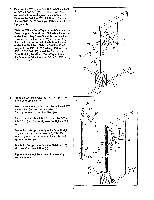
EXPLODED DRAWING Model No. WG93500 R794A 48 48 38 47 45 4 43 80 86 38-10 c`r%5 95 44 6 82-i 23 79 80 ciP-29 18 91 67 '\ 4 106- 110 77 6 63 et/ 115 70 118 4 97 57 5 63- 114 v. -is64 92 77 45 18 110 4 -4' 4 45,- 4 'O. 64 5 6 4 7 76 7 45 84 45 115 104 78 103 5 43 88 - Weider Pro 9350 | English Manual - Page 24
41 44k. 1189 60 58 • 20 • 83 69 • ,3 64 -119 7 64 68 65 111 91 43 29 0 e4 5 105 1,6-24 43 66 5 23 ' 4 2 54 4 41\4 4- 25 26 64 29 49 81 63,v 1150 23 28 51 V-29 55 64 27 81 52 481 /29 50
-
 1
1 -
 2
2 -
 3
3 -
 4
4 -
 5
5 -
 6
6 -
 7
7 -
8
-
9
-
10
-
11
-
12
-
13
-
14
-
15
-
16
-
17
-
18
-
19
-
20
-
21
-
22
-
23
-
24
 |
 |

X'
t$•
MULTI -STATION
PROFESSIONAL QUALITY FITNESS SYSTEM
Model
No.
WG93500
Serial
No.
Serial
Number
Decal
(Under
Seat)
QUESTIONS?
As
a
manufacturer,
we
are
com-
mitted
to
providing
complete
customer
satisfaction.
If
you
have
questions,
or
find
there
are
missing
or
damaged
parts,
we
will
guarantee
you
complete
satisfaction
through
direct
assistance
from
our
factory.
TO
AVOID
UNNECESSARY
DELAYS,
PLEASE
CALL
DIRECT
TO
OUR
TOLL
-FREE
CUSTOMER
HOT
LINE.
The
trained
technicians
on
our
customer
hot
line
will
provide
immediate
assistance,
free
of
charge
to
you.
CUSTOMER
HOT
LINE:
1400-225-0653
Mon.
-Fri.,
6
a.m.-6
p.m.
MST
CAUTION!
Read
all
safety
precautions
and
instructions
in
this
owner's
manual
before
using
this
equip-
ment.
Save
this
owner's
manual
for
future
reference.
PATENT
PENDING
0
0
OWNER'S
MANUAL
d