Weider Pro 9350 English Manual - Page 14
Adjustment
 |
View all Weider Pro 9350 manuals
Add to My Manuals
Save this manual to your list of manuals |
Page 14 highlights
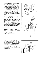
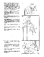
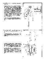
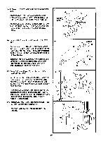
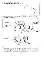
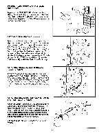
ADJUSTMENT The instructions below describe how each part of the hard drive system can be adjusted. Refer to the EXERCISE GUIDE accompanying this owner's manual to see how the hard drive system should be set up for each exercise. IMPORTANT: When attaching the let bar or nylon strap, make sure that the attachments are in the correct starting position for the exercise to be performed. If there is any slack in the cables or chain as an exercise is performed, the effectiveness of the exercise will be reduced. SELECTING THE WEIGHT SETTING The weight setting can be changed by moving the "L"- Pin (112) to different positions in the weight stack. The Large Weight (61) on top of the weight stack is perma- nently attached; if the "L"-Pin is not inserted, the weight setting will be 20 pounds. Each of the Weights (107) weighs 10 pounds. To change the weight set- ting, insert the "L"-Pin (112) under the desired Weight until the bent end of the "L"-Pin is touching the Weights. Turn the bent end downward. The weight 61 setting can be changed from 20 pounds to 150 pounds, in increments of 10 pounds. Note: Due to the cables and pulleys, the actual amount of resis- 107 tance at each exercise station may vary from the weight setting. 112 CHANGING THE ARMS TO THE BUTTERFLY MODE OR THE PRESS MODE The left and right Arms (27) can be used in either the butterfly mode or the press mode. To perform the BUTTERFLY exercise, change the Arms to the butterfly mode by turning the Selector Knob (24) clockwise. To perform the BENCH PRESS exercise, change the Arms to the press mode by turning the Selector Knob counterclockwise. ADJUSTING THE BACKREST The Large Backrest (30) can be adjusted to any of three positions. To change the position, first remove the 5/16" Knob (11) and 5/16" x 2 3/4" Carriage Bolt (113). Pivot the lower end of the Large Backrest until one of the three holes in the Adjustment Bracket (22) is aligned with the hole In the Front Upright (19). Insert the Carriage Bolt through the Adjustment Bracket and the Front Upright, and tighten the Knob onto the Carriage Bolt. 14 fa? 24 go 27 11 22 30 0 113 19 0 na
-
 1
1 -
2
-
3
-
4
-
5
-
6
-
7
-
8
-
 9
9 -
 10
10 -
 11
11 -
 12
12 -
 13
13 -
 14
14 -
 15
15 -
 16
16 -
 17
17 -
 18
18 -
 19
19 -
20
-
21
-
22
-
23
-
24
 |
 |
