Weider Pro 9735 English Manual
Weider Pro 9735 Manual
 |
View all Weider Pro 9735 manuals
Add to My Manuals
Save this manual to your list of manuals |
Weider Pro 9735 manual content summary:
- Weider Pro 9735 | English Manual - Page 1
® Model No. 831.159390 Serial No. The serial number can be found in the location shown below. Write the serial number in the space above. Serial Number Decal Patent Pending CAUTION Read all precautions and instructions in this manual before using this equipment. Save this manual for future - Weider Pro 9735 | English Manual - Page 2
2 IMPORTANT PRECAUTIONS 3 BEFORE YOU BEGIN 4 ASSEMBLY 5 HOW TO USE THE HOME GYM SYSTEM 26 WEIGHT RESISTANCE CHART 28 TROUBLE-SHOOTING AND MAINTENANCE 29 CABLE DIAGRAMS 30 ORDERING REPLACEMENT PARTS Back Cover Note: A PART IDENTIFICATION CHART and a PART LIST/EXPLODED DRAWING are attached to - Weider Pro 9735 | English Manual - Page 3
the home gym system in any commercial, rental or institutional setting. WARNING: Before beginning this or any exercise program, consult your physician. This is especially important for persons over the age of 35 or persons with pre-existing health problems. Read all instructions before using. SEARS - Weider Pro 9735 | English Manual - Page 4
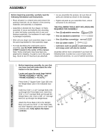
manual carefully before using the WEIDER® PRO 9735 Home Gym System. If you have additional questions, please call our toll- Before reading further, please review the drawing below and familiarize yourself with the parts that are labeled. High Pulley Station Lat Bar ASSEMBLED DIMENSIONS: Height - Weider Pro 9735 | English Manual - Page 5
information and instructions: • Place all parts in a cleared area and remove the packing materials; do not dispose of the packing materials until assembly is completed. • Assembly is divided into four stages: 1) frame assembly, 2) press and butterfly arm assembly, 3) cable and pulley assembly and - Weider Pro 9735 | English Manual - Page 6
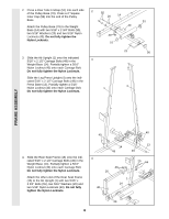
side 2 of the Pulley Base (79). Press a 2" Square Inner Cap (56) into the end of the Pulley Base. Attach the Pulley Base (79) to the Weight Base (14) with 51 56 FRAME ASSEMBLY 40 40 4. Slide the Rear Seat Frame (16) onto the indicated 5/16" x 2 1/2" Carriage Bolts (49) in the Weight Base (14 - Weider Pro 9735 | English Manual - Page 7
FRAME ASSEMBLY 5. Slide the Front Seat Frame (8) onto the indicated 5/16" x 2 1/2" Carriage Bolts the other Weight Guides (23) to the Weight Base (14) in the same manner. 7. Slide a Weight Bumper (27) onto each of the Weight Guides (23). Slide eight Weights (90) onto each set of Weight Guides (23). - Weider Pro 9735 | English Manual - Page 8
(90). Be sure that the pins on the Weight Tubes are in the pin grooves in the upper Weights. 25 26 90 90 FRAME ASSEMBLY 9. Lubricate the insides of the holes in the Top 9 Weights (24) as shown. Slide a Top Weight onto each set of Weight Guides (23). 24 Lubricate 23 23 Lubricate 24 8 - Weider Pro 9735 | English Manual - Page 9
Support Plate (98) and two 5/16" Nylon Locknuts (40). Do not tighten the Nylon Locknuts yet. 12. Attach the upper ends of one set of Weight Guides upper ends of the other set of Weight Guides (23) in the same manner. Before continuing, firmly tighten all nylon locknuts used in steps 2 through 12. 10 - Weider Pro 9735 | English Manual - Page 10
as shown. Press two 2" Square Inner Caps (56) into the Leg Press Arm (9). 14 73 9 10 11 56 ARM ASSEMBLY 15. Locate and open the parts bag labeled 15 "ARM ASSEMBLY." Attach the Large Bumper (53) to the Front Seat Frame (8) with the #10 x 1" Tap Screw (100). Lubricate the 3/8" x 3 1/4" Bolt - Weider Pro 9735 | English Manual - Page 11
Left Arm is behind the indicated bracket on the Butterfly Frame (3). IMPORTANT NOTE: Before assembling the 1" Retainers (45) used in this step, be sure that you thoroughly understand the step. The Retainers can be assembled only once. If they must be removed, you will need to order new Retainers - Weider Pro 9735 | English Manual - Page 12
(6). Wet the lower end of the Left Arm with soapy water. Slide a 10" Pad (22) onto the Left Arm. Repeat this step with the Right Arm (5). 5 22 6 48 22 ARM ASSEMBLY 21. Press a 1 3/4" Square Inner Cap (48) into the top of the Leg Lever Frame (30). 21 Slide the Leg Lever Frame - Weider Pro 9735 | English Manual - Page 13
Locate and open the parts bags labeled 23 "CABLE ASSEMBLY" and "PULLEYS." During steps 23 through 58, refer to the CABLE DIAGRAMS on pages 30 and 31 of this manual to verify proper cable routing. Before beginning this section, fully unwind the five Cables and identify the Cables by comparing the - Weider Pro 9735 | English Manual - Page 14
oriented as shown and be positioned to hold the Cable in the groove of the Pulley. 80 50 42 82 85 4 CABLE ASSEMBLY 28. Note: The Left Arm (6) is shown removed 28 for easier part identification. Slide the other end of the Butterfly Cable (85) onto a 3/8" x 1" 77 Bolt (77). Insert the Bolt - Weider Pro 9735 | English Manual - Page 15
CABLE ASSEMBLY 29. Note: The 3 1/2" Pulley (82) in this step is 29 pre-assembled. It is shown removed for easier part identification. Locate the High Cable (86)-this is the shortest remaining Cable. Route the High Cable around the 3 1/2" Pulley (82) attached to the Top Frame (2). Be sure that - Weider Pro 9735 | English Manual - Page 16
Bracket (32) to the indicated Weight Tube (25) with a 5/16" x 1 3/4" Bolt (68) and a 5/16" Nylon Locknut (40). 34. Locate the Rear Cable (87)-this is again the shortest remaining Cable. Wrap the Rear Cable around a 3 1/2" Pulley (82). Attach the Pulley and two Pulley Covers (62) to the Ab Upright - Weider Pro 9735 | English Manual - Page 17
) attached to the Pulley Plates (31). The Cable must be routed from the direction shown. Refer to the inset draw- ing. Be sure that the Cable is between the Cable Trap (80) and the Pulley, and that the Cable Trap is positioned to hold the Cable in place. 31 50 82 87 CABLE ASSEMBLY 80 87 37 - Weider Pro 9735 | English Manual - Page 18
Bolt. 40 61 39 20 92 89 50 40 42 89 83 81 57 Row Tube 97 79 Ball 14 41. Wrap the Low Cable (89) around a 3 1/2" Pulley (82). Attach the Pulley to the bracket 41 on the Weight Base (14) with a 3/8" x 2" Bolt (50) and a 3/8" Nylon Locknut (42). 89 50 82 42 14 18 - Weider Pro 9735 | English Manual - Page 19
on the Top Frame (2) with a 3/8" x 2" Bolt (50) and a 3/8" Nylon Locknut (42). The Cable must be routed from the direction shown. 2 42 50 82 89 CABLE ASSEMBLY 43. See the inset drawing. Attach a 3 1/2" Pulley (82) and a Cable Trap (80) to the upper hole 43 in the Large "U" Bracket (84 - Weider Pro 9735 | English Manual - Page 20
Nylon Locknut, as shown in the inset drawing. 88 47. Note: The 3 1/2" Pulley (82) in this step is 47 pre-assembled. It is shown dis-assembled for easier part identification. Route the Press Cable (88) around the 3 1/2" Pulley (82) attached to the indicated bracket on the Press Base (13). Be - Weider Pro 9735 | English Manual - Page 21
(82) in this step is pre-assembled. It is shown dis-assembled for easier part identification. Route the Press Cable (88) around the 3 1/2" Pulley (82) attached to the indicated bracket on the Press Base (13). Be sure that the Cable is in the groove of the Pulley and that the Cable Trap (80) is - Weider Pro 9735 | English Manual - Page 22
4 CABLE ASSEMBLY 88 43 53. Wrap the Press Cable (88) around a 3 1/2" 53 Pulley (82). Attach the Pulley and a Cable Trap Pulley (82) with a Cable Trap (80) onto the 3/8" x 4 1/2" Bolt (74). Hand tighten a 3/8" Nylon Jam Nut (43) onto the Bolt. Do not fully tighten the Nylon Locknut until step - Weider Pro 9735 | English Manual - Page 23
is turned to hold the Cable in place and that the Cable and Pulley move smoothly. 83 65 81 57. Note: The 3 1/2" Pulley (82) used in this step was attached in step 55. It is shown 57 removed for easier part identification. Route the Press Cable (88) around the 3 1/2" Pulley (82). Be sure that - Weider Pro 9735 | English Manual - Page 24
3/4" Screws (59). 17 8 41 60 59 37 64 44 1 59 18 SEAT ASSEMBLY 62. Insert a 1/4" x 2 1/2" Carriage Bolt (60) through the center hole in the Rear Seat Frame (16) with a 1/4" Washer (37) and a 1/4" x 2 1/2" Machine Screw (64). 63. Press 3/4" Round Inner Caps (78) into the ends of each Pad - Weider Pro 9735 | English Manual - Page 25
remaining parts will be explained in HOW TO USE THE HOME GYM SYSTEM, beginning on page 26 of this manual. Before using the home gym system, pull each cable a few times to be sure that the cables move smoothly over the pulleys. If one of the cables does not move smoothly, find and correct the problem - Weider Pro 9735 | English Manual - Page 26
HOW TO USE THE HOME GYM SYSTEM The instructions below describe how each part of the home gym system can be adjusted. Refer to the exercise poster accompanying this manual to see how the home gym system should be set up for each exercise. IMPORTANT: When attaching the lat bar, row bar, ab strap, or - Weider Pro 9735 | English Manual - Page 27
Attach the Ab Strap (35) to the Rear Cable (87) at the ab pulley station with a Cable Clip (33). 33 35 ADJUSTING THE LEG LEVER the Adjustment Tube (10). Align the holes in the Leg Press Arm (9) with the desired set of holes in the Adjustment Tube (10). Reinsert the Lock Pin (73) through the holes - Weider Pro 9735 | English Manual - Page 28
151 LEG PRESS (lbs.) AB PULLEY (lbs.) 62 16 132 33 190 46 244 61 293 77 336 91 377 107 430 126 480 135 The actual resistance at each weight station may vary due to differences in individual weight plates, as well as friction between the cables, pulleys and weight guides. 28 - Weider Pro 9735 | English Manual - Page 29
TROUBLE-SHOOTING AND MAINTENANCE Inspect and tighten all parts each time you use the home gym system. Replace any worn parts immediately. The home gym system can be cleaned using a damp cloth and mild non-abrasive detergent. Do not use solvents. TIGHTENING THE CABLES Woven cable, the type of - Weider Pro 9735 | English Manual - Page 30
The numbers show the proper route for each Cable. IMPORTANT: If the Cables have not been correctly routed, the WEIDER PRO 9735 will not function properly and damage may occur. Press Cable (88) High Cable (86) 4 2 3 High Pulley-1 1-Long "U" Bracket 4 Weight Stack-5 5 76 11 8 2 3 9 12 10 - Weider Pro 9735 | English Manual - Page 31
Low Cable (89) 6 4 5 Weight Stack-7 Rear Cable (87) 3 Ab Pulley-1 2 5-Leg Lever 3 4 1-Low Pulley 2 31 - Weider Pro 9735 | English Manual - Page 32
1" x 7/8" Plastic Bushing (54) 3/4" Round Inner Cap (78) 1" Round Inner Cap (70) 1 1/8" x 2 1/2" Plastic Bushing (47) 1/2 x 3/4" Spacer (69) 5/8" x 9/16" Plastic Bushing (61) 1" Round Outer Cap (46) 1" Retainer (45) 1 3/4" Square Inner Cap (48) 2" Square Outer Cap (58) 2" Square Inner Cap ( - Weider Pro 9735 | English Manual - Page 33
Bolt (68) 3/8" x 1" Bolt (77) 1/4" x 2 1/2" Carriage Bolt (60) 5/16" x 2 1/2" Carriage Bolt (49) 1/4" x 2 1/2" Machine Screw (64) Cable Clip (33) "V" Pulley (81) (Not shown to scale) 3 1/2" Pulley (82) (Not shown to scale) 3/8" x 4" Carriage Bolt (57) 3/8" x 3 1/2" Bolt (66) 3/8" x 4" Bolt (76 - Weider Pro 9735 | English Manual - Page 34
Butterfly Cable High Cable Rear Cable Press Cable Low Cable Weight 5/16" Nylon Jam Nut 5/16" x 3" Bolt Weight Pin Row Bar Small Bumper Large Lock Pin 3 1/2" Pro Pulley Support Plate 1/4" x 5/8"" Screw #10 x 1" Tap Screw User's Manual Exercise Poster Note: "#" indicates a non-illustrated part - Weider Pro 9735 | English Manual - Page 35
EXPLODED DRAWING-Model No. 831.159390 R0698A 21 21 78 29 48 43 15 87 40 61 78 29 55 42 56 55 20 40 40 20 20 42 43 42 - Weider Pro 9735 | English Manual - Page 36
the following information: • The MODEL NUMBER of the product (831.159390). • The NAME of the product (WEIDER® PRO 9735 Home Gym System). • The KEY NUMBER and DESCRIPTION of the PART (see the PART LIST/EXPLODED DRAWING at the center of this manual). REPLACEMENT PARTS If parts become worn and need to
-
 1
1 -
 2
2 -
 3
3 -
 4
4 -
 5
5 -
 6
6 -
 7
7 -
8
-
9
-
10
-
11
-
12
-
13
-
14
-
15
-
16
-
17
-
18
-
19
-
20
-
21
-
22
-
23
-
24
-
25
-
26
-
27
-
28
-
29
-
30
-
31
-
32
-
33
-
34
-
35
-
36
 |
 |

Patent Pending
®
Model No. 831.159390
Serial No.
The serial number can be found in the
location shown below. Write the serial
number in the space above.
CAUTION
Read all precautions and instruc-
tions in this manual before using
this equipment. Save this manual
for future reference.
USER’S MANUAL
Serial Number Decal
SEARS, ROEBUCK AND CO., HOFFMAN ESTATES, IL 60179