Weider Pro 9935 English Manual
Weider Pro 9935 Manual
 |
View all Weider Pro 9935 manuals
Add to My Manuals
Save this manual to your list of manuals |
Weider Pro 9935 manual content summary:
- Weider Pro 9935 | English Manual - Page 1
satisfaction. If you have questions, or if there are missing parts, we will guarantee complete satisfaction through direct assistance from our and instructions in this manual before using this equipment. Save this manual for future reference. Patent Pending USERÕS MANUAL THIS MANUAL RECEIVED - Weider Pro 9935 | English Manual - Page 2
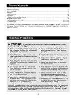
to tip. 2. Read all instructions in this manual and in the accompanying literature before using the home gym. 3. If you feel pain or dizziness at any time while exercising, stop immediately and begin cooling down. 8. Keep hands and feet away from moving parts. 9. Keep children under the age of 12 - Weider Pro 9935 | English Manual - Page 3
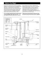
). For your benefit, read this manual carefully before using the WEIDER¨ PRO 9935 Home Gym. If you have additional questions, please call our Customer Please use the drawing below to familiarize yourself with the major parts and how they fit together. ASSEMBLED DIMENSIONS: Height: 77 in. Width - Weider Pro 9935 | English Manual - Page 4
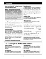
: Wait until you begin each assembly stage to open the parts bag labeled for that assembly stage. Some assembly steps require two people. Tightening Parts Tighten all parts as you assemble them, unless instructed to do otherwise. Lining Up the Tools Assembly requires the following tools (not - Weider Pro 9935 | English Manual - Page 5
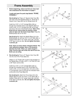
and understood the information on page 4. Locate and open the parts bag labeled ÒFRAME ASSEMBLY.Ó See drawing 1a. Press a 2Ó Square Inner Cap (28 Base (6) to the Weight Base (5) with two 5/16Ó x 2 3/4Ó Bolts (89), a Support Plate with 3 1/2Ó center holes (93), and two 5/16Ó Nylon Locknuts (64). Do - Weider Pro 9935 | English Manual - Page 6
33). 89 86 Attach the Butterfly Top Frame (33) to the indicated bracket at the top of the Butterfly Upright (1) with two 5/16Ó x 2 3/4Ó Bolts (89), a Support Plate with 3 1/2Ó center holes (93), and two 5/16Ó Nylon Locknuts (64). 28 33 64 93 28 28 5. Attach the Butterfly Seat Frame (14) to the - Weider Pro 9935 | English Manual - Page 7
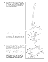
16Ó Nylon Locknuts (64) onto the Bolts. Do not tighten the Nylon Locknuts yet. Place the bracket on the lower end of the Support Frame (3) over the indicated 3/8Ó x 2 1/2Ó Carriage Bolt (101) and the 3/8Ó x 4Ó Carriage Bolt (102) in the Press Base (6). Hand tighten a 3/8Ó Nylon Jamnut (63) onto the - Weider Pro 9935 | English Manual - Page 8
(48), and a 3/8Ó Nylon Locknut (50). Slide six Weights (21) onto the Weight Guides (15). Make sure the Weights are turned so the pin grooves point towards the floor. Press in the Weights (21). Slide a Top Weight (16) onto the Weight Guides (15). Note: Make sure the Top Weight is turned so the groove - Weider Pro 9935 | English Manual - Page 9
in the Weights (21). Slide a Top Weight (16) onto the Weight Guides (15). Note: Make sure the Top Weight is turned so the groove fits 66) to the Butterfly Top Frame (33) with two 3/8Ó x 2 3/4Ó Bolts (46), a Support Plate with 4Ó center holes (94), and two 3/8Ó Nylon Locknuts (50). Do not tighten the - Weider Pro 9935 | English Manual - Page 10
Weight Guides (15) to the Weight Top Frame (66) with a 3/8Ó x 3 3/4Ó Bolt (59), a 3/8Ó Flat Washer (48), and a 3/8Ó Nylon Locknut (50). Important: Go back and fully tighten all Nylon Locknuts used in steps 1 through 15. 15 59 48 59 15 50 50 48 15 Arm Assembly 16 16. Locate and open the parts - Weider Pro 9935 | English Manual - Page 11
Left Butterfly Arm (10, not shown). 18 11 35 33 Axle 35 31 38 29 Cable Assembly 19. Locate and open the parts bag labeled ÒCABLE 19 ASSEMBLY AND PULLEYS.Ó For Cable identifica- tion and routing during steps 19 to 49, refer to the Cable Diagrams and Cable ID Chart on pages 23 - Weider Pro 9935 | English Manual - Page 12
21. Remove both 3 1/2Ó Pulleys (24) from the pre-assem- 21 bled Small Pulley Bracket (22). Wrap the Butterfly Cable (73) around a 3 1/2Ó Pulley (24) in the direction shown. Attach the Pulley to the Small Pulley Bracket (22) with a 3/8Ó x 1 3/4Ó Bolt (57) and a 3/8Ó Nylon Locknut (50). Make sure the - Weider Pro 9935 | English Manual - Page 13
25. Remove both 3 1/2Ó Pulleys (24) from the pre-assembled Adjustable Pulley Plates (23). Wrap the Ab Cable (74) around a 3 1/2Ó Pulley (24) in the direction shown. Attach the Pulley and a Cable Trap (25) to the - Weider Pro 9935 | English Manual - Page 14
on the Weight Base (5). Make sure the Cable is routed in the direction shown. 4 Note: For clarity, this and the following drawings show some parts removed. 29. Wrap the Ab Cable (74) around a 4 1/2Ó Pulley (82) in 29 the direction shown. Attach the Pulley inside the indicated bracket on the - Weider Pro 9935 | English Manual - Page 15
and a loop on the other. Route the end with the loop through the slot in the cable guide on the Butterfly Base (4). Route the Low Pulley Cable (75) under a Pro Pulley (26) as shown. Attach the Pro Pulley and a Cable Trap (25) to the bracket on the Butterfly Base (4) with a 3/8Ó x 2Ó Bolt (54) and - Weider Pro 9935 | English Manual - Page 16
one end and a threaded 36 shaft on the other. You will begin by attaching the end with the ball. Wrap the Press Cable (72) around a Pro Pulley (26) 63 in the direction shown. Attach the Pulley to the indi- cated hole in the Press Top Frame (9) with a 3/8Ó x 48 3 1/2Ó Bolt (56), a 3/8Ó Flat - Weider Pro 9935 | English Manual - Page 17
39. Important: Although the following steps are not 39 difficult to perform, the correct routing of the cable is critical to the functioning of the home gym. Please make sure that you wrap the cable around the pulleys exactly as shown in each step. Route the Press Cable (72) through the - Weider Pro 9935 | English Manual - Page 18
43. Wrap the Press Cable (72) around a 3 1/2Ó Pulley 43 (24) in the direction shown. Attach the Pulley and a Cable Trap (25) to the indicated hole on the far side 72 of the Leg Press Lever (83) with a 3/8Ó x 4 3/4Ó Bolt (60) and a 3/8Ó Nylon Jamnut (63). Note: Thread the 60 Jamnut only two - Weider Pro 9935 | English Manual - Page 19
47. Route the threaded end of the Press Cable (72) 47 around the 3 1/2Ó Pulley (24) that was mounted on the bracket on the Weight Base (5) in an earlier step. 72 24 5 48. Wrap the Press Cable (72) over a 4 1/2Ó Pulley (82) 48 in the direction shown. Attach the Pulley inside the indicated - Weider Pro 9935 | English Manual - Page 20
50 50. Locate and open the parts bag labeled ÒSEAT ASSEMBLY.Ó Attach the Backrest (12) to the indicated holes in the Butterfly Upright (1) with two 1/4Ó x 2 1/2Ó Bolts (79) and two 1/4Ó Flat Washers (71). 12 1 79 71 79 - Weider Pro 9935 | English Manual - Page 21
other Seat (13) to the Press Seat Frame (7, not shown) in the same manner. 52 13 45 65 14 49 71 68 71 79 Miscellaneous Assembly 53. Press a 3/4Ó Round Inner Cap (43) into each end of the two Pad Tubes (42). Insert one Pad Tube (42) into the indicated hole in - Weider Pro 9935 | English Manual - Page 22
Apply the new decal in the appropriate location. 55 WEIDER PRO 9935 56. Make sure that all parts have been properly tightened. The use of the remaining parts will be explained in ADJUSTMENT, beginning on page 25 of this manual. Before using the home gym, pull each cable a few times to make sure that - Weider Pro 9935 | English Manual - Page 23
that the Pulleys move smoothly, and that the Cable Traps do not touch or bind the Cables. Incorrect cable routing can damage the home gym. Low Pulley Cable (75) Ab Cable (74) 7 3 3 1 2 2 1 4 5 8 5 4 Butterfly Cable (73) 6 4 1 5 2 Cable ID Chart 73, 52Ó 75, 143.5Ó 3 74, 224Ó 72, 389 - Weider Pro 9935 | English Manual - Page 24
Press Cable (72) 14 2 1 15 8 10 5 6 9 4 13 12 3 7 11 24 - Weider Pro 9935 | English Manual - Page 25
Adjustment The instructions below describe how each part of the home gym can be adjusted. Refer to the exercise poster accompanying this manual to see how the home gym should be set up for each exercise. IMPORTANT: When using an attachment, make sure it is in the correct starting position for the - Weider Pro 9935 | English Manual - Page 26
Trouble-shooting and Maintenance Inspect and tighten all parts each time you use the home gym. Replace any worn parts immediately. The home gym can the cables need to be replaced, see ORDERING REPLACEMENT PARTS on the back cover of this manual. Slack can be removed from the cables in several - Weider Pro 9935 | English Manual - Page 27
: The actual resistance at each station may vary due to differences in individual weight plates as well as friction between the cables, pulleys, and weight guides. Weight Plates Top 1 2 3 4 5 6 7 8 9 10 High Pulley (lbs.) 14 28 42 55 69 83 97 111 124 138 152 Arm Press (lbs.) 16 37 58 78 - Weider Pro 9935 | English Manual - Page 28
1Ó Retainer Ring (31) 3/4" Round Inner Cap (43) 1" Round Inner Cap (86) 1" Square Inner Cap (98) 1" Round Outer Cap (38) 1" Round Inner Cap (76) 1 3/4" Square Inner Cap (35) 2" Square Inner Cap (28) - Weider Pro 9935 | English Manual - Page 29
Part Identification ChartÐModel No. WESY99490 R0999B 1/4" Nylon Locknut (68) 5/16" Nylon Locknut (64) 5/16" x 1 3/4" Bolt (96) 3/8" Nylon Locknut (50) 3/8" Nylon Jamnut (63) 5/16" x 2 1/2" Bolt (87) 5/ - Weider Pro 9935 | English Manual - Page 30
3/8" x 8" Bolt (52) 3/8" x 4 3/4" Bolt (60) 3/8" x 2 3/4" Bolt (46) 3/8" x 3" Bolt (88) 3/8" x 3 1/4" Bolt (62) 3/8" x 3 1/2" Bolt (56) 3/8" x 3 1/2" Carriage Bolt (95) 3/8" x 3 3/4" Bolt (59) 3/8" x 4" Bolt (78) 3/8" x 4" Carriage Bolt (102) 3/8" x 4 1/4" Bolt (85) - Weider Pro 9935 | English Manual - Page 31
Weight Guide 67 2 Pro Pulley Support Plate, 4Ó Center Holes 3/8Ó x 3 1/2Ó Carriage Bolt 5/16Ó x 1 3/4Ó Bolt ÒUÓ-bracket 1Ó Square Inner Cap Press Backrest Plastic Bushing 3/8Ó x 2 1/2Ó Carriage Bolt 3/8Ó x 4Ó Carriage Bolt UserÕs Manual Exercise Poster Note: Ò#Ó indicates a non-illustrated part - Weider Pro 9935 | English Manual - Page 32
84 37 11 73 94 93 46 28 84 37 63 35 31 38 31 38 35 86 73 63 10 89 28 53 64 33 27 32 28 50 1 59 48 29 12 43 30 35 60 24 29 25 13 28 65 64 14 45 49 50 53 32 50 27 15 47 74 24 47 48 97 74 63 71 96 79 16 36 17 89 36 25 24 18 63 64 21 19 46 34 50 50 50 50 - Weider Pro 9935 | English Manual - Page 33
WEIDER¨ PRO 9935 Home Gym System) 3. The SERIAL NUMBER of the product (see the front cover of this manual) 4. The KEY NUMBER and DESCRIPTION of the part(s) (see the PART abnormal usage or repairs not provided by an ICON authorized service center, products used for commercial or rental purposes, or
-
 1
1 -
 2
2 -
 3
3 -
 4
4 -
 5
5 -
 6
6 -
 7
7 -
8
-
9
-
10
-
11
-
12
-
13
-
14
-
15
-
16
-
17
-
18
-
19
-
20
-
21
-
22
-
23
-
24
-
25
-
26
-
27
-
28
-
29
-
30
-
31
-
32
-
33
 |
 |
¤
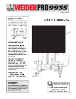
USER°S MANUAL
Model No. WESY99490
Serial No.
The serial number is found in the
location shown below. Write the
serial number in the space above.
CAUTION
Read all precautions and instruc-
tions in this manual before using
this equipment. Save this manu-
al for future reference.
Serial
Number
Decal
Patent Pending
QUESTIONS?
As a manufacturer, we are
committed to providing com-
plete customer satisfaction. If
you have questions, or if there
are missing parts, we will guar-
antee complete satisfaction
through direct assistance from
our factory.
TO AVOID UNNECESSARY
DELAYS, PLEASE CALL
DIRECT TO OUR TOLL-FREE
CUSTOMER HOT LINE. The
trained technicians on our cus-
tomer hot line will provide
immediate assistance, free of
charge to you.
CUSTOMER HOT LINE:
1-800-999-3756
Mon.—Fri., 6 a.m.—6 p.m. MST
Visit our website at
www.weiderfitness.com
new products, prizes,
fitness tips, and much more!
THIS MANUAL RECEIVED
SEVERAL DRAWING
CHANGES AFTER IT PRINT-
ED FOR CUSTOMER USE.
THE DRAWING CHANGES
WERE MADE AND THE REV.
DATE WAS CHANGED TO
R0999B, BUT THE MANUAL
HAS NOT PRINTED AGAIN.