Weider X5 Power Guide English Manual - Page 13
Nylon, Washer, Square, Plastic, Insert
 |
View all Weider X5 Power Guide manuals
Add to My Manuals
Save this manual to your list of manuals |
Page 13 highlights
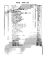
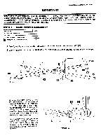
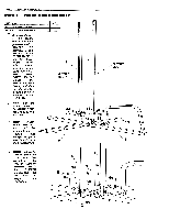
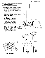
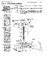
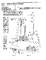
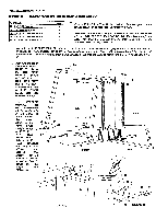
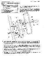
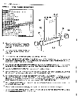
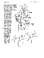
PAGE 11 WEIDER SPORTING GOODS STEP 4 MAIN UPRIGHT ASSEMBLY PART NAME 51 5/16" NYLON LOCK NUT 55 5/16" X 21/4" HEX HEAD BOLT 60 3/8" FLAT WASHER 61 3/8" NYLON LOCK NUT 62 3/8" X 4 3/4" HEX HEAD BOLT 80 2" SQUARE PLASTIC INSERT CAP 81 2" x 4" PLASTIC INSERT CAP QTY 1 1 2 1 1 1 1 Press a 2" X 4" PLASTIC INSERT CAP (81) into the TOP MAIN UPRIGHT (11). Press a 2" SQUARE PLASTIC INSERT CAP (80) into the TOP MAIN UPRIGHT (11). Assemble the top of the MAIN UPRIGHT (11) to the top of the GUIDE RODS (4) by straddling the Welded Brackets on the Upright over the Guide Rods. At the same time, straddle the bottom of the Main Upright over the FRONT BASE (2). CI Bolt ONLY the front GUIDE ROD (4) to the Welded Brackets on the UPRIGHT (11) using a 5/16" X 2 1/4" HEX HEAD BOLT (55) to bolt through one Bracket, through the Guide Rod, and then through the other Bracket. Secure with a 5/16" NYLON LOCK NUT (51). Assemble the bottom of the MAIN UPRIGHT (11) to the FRONT BASE (2) by first assembling a 3/8" FLAT WASHER (60) onto a 3/8" X 4 3/4" HEX HEAD BOLT (62) and then bolting through the Upright and then through the Welded Bushing on the Base. Assemble another 3/8" FLAT WASHER (60) onto the Bolt and secure with a 3/8" NYLON LOCK NUT (61). CI Remove the TOP MAST DECAL (100) from the backing sheet and position the Decal to the side of the TOP MAIN UPRIGHT (11) in between the two assembled Pulleys. PRE-ASSEMBLED PULLEY TOP MAIN UPRIGHT 11 PRE-ASSEMBLED PULLEY 81 ILI 0 100 80 51 WELDED BRACKETS 55 0 11 4 4 0 O 61 60 \O- 0 o 0 2 FRONT WELDED 60 62 BUSHING REAR
-
 1
1 -
2
-
3
-
4
-
5
-
6
-
7
-
 8
8 -
 9
9 -
 10
10 -
 11
11 -
 12
12 -
 13
13 -
 14
14 -
 15
15 -
 16
16 -
 17
17 -
 18
18 -
19
-
20
-
21
-
22
-
23
-
24
-
25
-
26
-
27
-
28
-
29
-
30
-
31
-
32
-
33
-
34
-
35
-
36
 |
 |
