Weslo 1000 Uk Manual
Weslo 1000 Manual
 |
View all Weslo 1000 manuals
Add to My Manuals
Save this manual to your list of manuals |
Weslo 1000 manual content summary:
- Weslo 1000 | Uk Manual - Page 1
if there are missing or damaged parts, please call: 08457 089 009 Or write: ICON Health & Fitness, Ltd. Unit 4 Revie Road Industrial Estate Revie Road Beeston Leeds, LS118JG UK email: [email protected] CAUTION Read all precautions and instructions in this manual before using this equipment. Save - Weslo 1000 | Uk Manual - Page 2
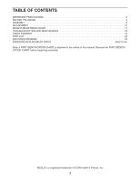
CHART 17 TROUBLESHOOTING AND MAINTENANCE 18 CABLE DIAGRAM 19 PART LIST 22 EXPLODED DRAWING 23 ORDERING REPLACEMENT PARTS Back Cover Note: A PART IDENTIFICATION CHART is attached in the centre of this manual. Remove the PART IDENTIFICATION CHART before beginning assembly. WESLO is a registered - Weslo 1000 | Uk Manual - Page 3
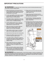
on all of the pulleys. WARNING: Before beginning this or any exercise program, consult your physician. This is especially important for persons over the age of 35 or persons with pre-existing health problems. Read all instructions before using. ICON assumes no responsibility for personal injury or - Weslo 1000 | Uk Manual - Page 4
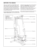
improve your cardiovascular system, the WESLO® GYM 1000 will help you to achieve the specific results you want. For your benefit, read this manual carefully before using the weight system. If you have questions after reading this manual, please call our Customer Service Department at 0845 089 009 - Weslo 1000 | Uk Manual - Page 5
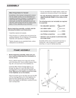
. • Tighten all parts as you assemble them, unless instructed to do otherwise. • As you assemble the weight system, make sure all parts are oriented as shown in the drawings. • For help identifying small parts, use the PART IDENTIFICATION CHART in the centre of this manual. The following tools - Weslo 1000 | Uk Manual - Page 6
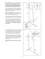
Inner Caps (49) into the top of the crossbar. Attach the Top Frame (55) to the Front Upright (42) with two M8 x 67mm Bolts (72), a Support Plate (8), and two M8 Nylon Locknuts (3). Attach the Top Frame to the Rear Upright (56) in the same manner. Tighten the Nylon Locknuts (3) used in - Weslo 1000 | Uk Manual - Page 7
ARM ASSEMBLY 4 4. Press a 25mm Plastic Bushing (26) onto each welded spacer on the Press Frame (17). Slide the Press Frame onto the Base (4) so the Plastic Bushings are aligned with the indicated tube in the base. Note: This will be a tight fit; the Plastic Bushings should fit over the ends of the - Weslo 1000 | Uk Manual - Page 8
the lower end of each Arm. 7 48 44 45 CABLE ASSEMBLY 8. During steps 9 through 22, refer to the CABLE DIAGRAM on page 19 of this manual to verify proper cable routing. Before beginning this section, identify the Short Cable (23) and the Long Cable (58) by comparing the ends of the - Weslo 1000 | Uk Manual - Page 9
10. Wrap the Long Cable (58) around a "V"-Pulley (6). Attach the Pulley and a Long Cable Trap (50) 10 to the bracket on the Front Upright (42) with an M10 x 60mm Bolt (7) and an M10 Nylon Locknut (21). Make sure that the Cable Trap is posi- tioned to hold the Cable in the groove of the Pulley. - Weslo 1000 | Uk Manual - Page 10
14. Wrap the Long Cable (58) under a 90mm Pulley (15). Attach the Pulley and a pair of Pulley Covers (73) to the upper hole in the Long "U"Bracket (57) with an M10 x 50mm Bolt (12) and an M10 Nylon Locknut (21). Make sure that the large tabs on the Pulley Covers are on the side shown. 14 73 Large - Weslo 1000 | Uk Manual - Page 11
17. Locate the Short Cable (23). Route the Short Cable through the bracket on the Press Frame (17), as shown. Make sure that the Cable is routed over the crossbar. Hold a 90mm Pulley (15) inside of the bracket on the Press Frame (17). Attach the Pulley to the Press Frame with an M10 x 198mm Bolt (59 - Weslo 1000 | Uk Manual - Page 12
21. Attach the end of the Short Cable (23) to the 21 Long "U"-Bracket (57) with an M8 Nylon Locknut (3) and an M8 Washer (68). Do not completely tighten the Nylon Locknut; it should be threaded onto the end of the Cable until two threads are showing above the Nylon Locknut, as shown in the - Weslo 1000 | Uk Manual - Page 13
23. Press a 38mm Square Inner Cap (32) into the Seat Frame (36). 23 Insert the M6 x 50mm Carriage Bolt (38) into the centre hole in the Seat Plate (37). Attach the Seat Plate to the Seat (13) with two M6 x 16mm Screws (18). Insert the M6 x 50mm Carriage Bolt (38) into the indicated hole in the - Weslo 1000 | Uk Manual - Page 14
the problem. IMPORTANT: If the cables are not properly routed, they may be damaged when heavy weight is used. See the CABLE DIAGRAM on page 19 of this manual for proper cable routing. If there is any slack in the cables, you will need to remove it by tightening the cables; see TROUBLESHOOTING - Weslo 1000 | Uk Manual - Page 15
The instructions below describe how each part of the weight system can be adjusted. IMPORTANT: When attaching the lat bar or nylon strap, make sure that the attachments are in the correct starting position for the exercise to be performed. If there is any slack in the cables or chain as an exercise - Weslo 1000 | Uk Manual - Page 16
Front Upright (42). Attach the Seat Frame to the Front Upright with the M8 x 67mm Carriage Bolt (14) and the Seat Knob (40). For some exercises, the Seat (13) must be removed. First, make sure that the chain is not attached to the leg lever. Next, remove the Seat Knob (40 - Weslo 1000 | Uk Manual - Page 17
WEIGHT RESISTANCE CHART This chart shows the approximate weight resistance at each weight station. The column labelled "WEIGHT" refers to the amount of weight, in pounds, placed on the weight carriage. The weight resistance shown for the butterfly arm station is for each butterfly arm. Note: The - Weslo 1000 | Uk Manual - Page 18
TROUBLESHOOTING AND MAINTENANCE Make sure all parts are properly tightened each time you use the weight system. Replace any worn parts immediately. The weight system can be cleaned to be replaced, see ORDERING REPLACEMENT PARTS on the back cover of this manual. 73 73 15 21 57 3 23 12 18 - Weslo 1000 | Uk Manual - Page 19
CABLE DIAGRAM The cable diagram below shows the proper routing of the Short Cable (23) and the Long Cable (58). Use the diagram to make sure that the two cables and the cable traps have been assembled correctly. If the cables have not been correctly routed, the weight system will not function - Weslo 1000 | Uk Manual - Page 20
NOTES 20 - Weslo 1000 | Uk Manual - Page 21
NOTES 21 - Weslo 1000 | Uk Manual - Page 22
Stop 68 1 M8 Washer 69 1 M10 x 20mm Bolt 70 3 Square Slider Bushing 71 2 M10 x 45mm Bolt 72 4 M8 x 67mm Bolt 73 10 Pulley Cover # 1 Userʼs Manual Note: "#" indicates a non-illustrated part. Specifications are subject to change without notice. 22 - Weslo 1000 | Uk Manual - Page 23
EXPLODED DRAWING-Model No. WLEVSY98110 R0702A 64 20 21 66 3 71 15 27 8 72 56 73 15 73 55 72 8 15 71 44 49 3 21 44 21 73 15 60 16 73 58 63 62 7 50 6 21 50 7 48 6 3 21 42 44 45 13 60 63 62 47 44 45 21 3 68 57 49 12 70 23 21 3 67 61 58 49 69 10 43 19 70 11 51 3 9 41 - Weslo 1000 | Uk Manual - Page 24
PART IDENTIFICATION CHART-Model No. WLEVSY98110 R0702A M10 Washer (9) 25mm Round Cover Cap (62) M6 x 16mm Screw (18) M10 x 20mm Bolt (69) M8 Washer (68) M6 x - Weslo 1000 | Uk Manual - Page 25
50mm Square Outer Cap (51) 50mm Square Inner Cap (27) 45mm Square Inner Cap (44) M6 x 63mm Screw (43) M10 x 60mm Bolt (7) M8 x 63mm Bolt (22) M8 x 63mm Carriage Bolt (1) M8 x 67mm Bolt (72) M8 x 70mm Bolt (11) M8 x 67mm CarriageBolt (14) M10 x 87mm Bolt (25) M10 x 97mm Bolt (16) M8 x 115mm Bolt (64 - Weslo 1000 | Uk Manual - Page 26
"V"-Pulley (6) (Not shown to scale) 90mm Pulley (15) (Not shown to scale) - Weslo 1000 | Uk Manual - Page 27
) • the NAME of the product (WESLO® GYM 1000 weight system) • the SERIAL NUMBER of the product (see the front cover of this manual) • the KEY NUMBER and DESCRIPTION of the part(s) (see the PART LIST and EXPLODED DRAWING on pages 22 and 23 of this manual). Part No. 188515 R0702A Printed in China
-
 1
1 -
 2
2 -
 3
3 -
 4
4 -
 5
5 -
 6
6 -
 7
7 -
8
-
9
-
10
-
11
-
12
-
13
-
14
-
15
-
16
-
17
-
18
-
19
-
20
-
21
-
22
-
23
-
24
-
25
-
26
-
27
 |
 |

USER'S MANUAL
CAUTION
Read all precautions and instruc-
tions in this manual before using
this equipment. Save this manual
for future reference.
Model No.WLEVSY98110
Serial No.
Write the serial number in the
space above for reference.
Serial Number Decal (under seat)
www.iconeurope.com
Visit our website at
QUESTIONS?
As a manufacturer, we are
committed to providing com-
plete customer satisfaction. If
you have questions, or if there
are missing or damaged parts,
please call:
Or write:
ICON Health & Fitness, Ltd.
Unit 4
Revie Road Industrial Estate
Revie Road
Beeston
Leeds, LS118JG
UK
email: [email protected]
08457 089 009