Weslo 400 Instruction Manual - Page 6
Assembly
 |
View all Weslo 400 manuals
Add to My Manuals
Save this manual to your list of manuals |
Page 6 highlights
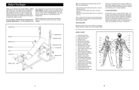
Assembly Before beginning assembly, read the following information and instructions carefully. Make Things Easier for Yourself Everything in this manual is designed to ensure that the weight bench can be assembled successfully by anyone. Most people find that by setting aside plenty of time, and by deciding to make the task enjoyable, assembly will go smoothly. • Assembly requires two people. • Place all parts in a cleared area and remove the packing materials. Do not dispose of the packing materials until assembly is completed. • Tighten all parts as you assemble them, unless instructed to do otherwise. • For help identifying the small parts, use the PART IDENTIFICATION CHART on page 5. • As you assemble the weight bench, make sure all parts are oriented as shown in the drawings. The following tools (not included) are required for assembly: • two adjustable spanners • one rubber mallet • one standard screwdriver • one phillips screwdriver • lubricant, such as grease or petroleum jelly, and soapy water. Assembly will be more convenient if you have the following tools: A socket set, a set of open-end or closed-end spanners or a set of ratchet spanners. 1. Before assembling this product, make sure that you have read and understand the information in 1 2 the box above. Press five 38mm Square Inner Caps (4) into the Base (3) as shown. 1 Unscrew the M8 x 45mm Bolts (1) from the "U"-brack- ets (2). Insert the Bolts up through the indicated holes in the Base (3). Place a "U"-bracket on each Bolt and hand tighten the Bolts. Do not fully tighten the Bolts yet. Make sure the "U"-brackets are orient- 4 ed as shown in the drawing. 34 4 4 2 3 1 2. Place the "H"-frame (5) over the two "U"-brackets (2) on the Base (3). Make sure that the "H"-frame is oriented correctly. The indicated round tubes must protrude on the side shown. Attach the "H"-frame (5) to the "U"-brackets (2) with two M8 x 52mm Bolts (6), four M8 Washers (23), and two M8 Nylon Locknuts (7). Do not fully tighten the Nylon Locknuts yet. 2 23 6 3 23 7 2 23 6 Protrusion 5 23 7 2 6 ADJUSTING THE BACKREST The Backrest (10) can be set to four different positions: a level position and three inclined positions. 10 To change the position of the Backrest (10), move the Adjustment Tube (12) to a different set of adjustment holes in the uprights. Rotate the Adjustment Tube to the locked position, with the locking pin wrapped around the "H"-frame (5). To set the Backrest (10) to a level position, remove the Adjustment Tube (12) and rest the Backrest on the "H"frame (5). ATTACHING WEIGHTS TO THE LEG LEVER 27 To use the Leg Lever (27), slide the desired amount of weight (not included) onto the Weight Tube (21). WARNING: Do not place more than 23 kg (50 lbs.) on the Leg Lever (27). 21 ADJUSTING THE HEIGHT OF THE LEG LEVER To adjust the height of the Leg Lever (27), remove the Large Adjustment Clip (20). Slide the Leg Lever Tube (18) to the desired position and re-insert the Large Adjustment 20 Clip. 12 5 18 27 LOCKING THE BARBELL To change weights whilst your barbell (not included) is on the uprights, secure your barbell with the Barbell Hooks (14, 40). This will reduce the possibility of the barbell tipping whilst you are changing weights. Always place the same amount of weight on both sides of the barbell. 14 11 Barbell 40
-
 1
1 -
 2
2 -
 3
3 -
 4
4 -
 5
5 -
 6
6 -
 7
7 -
 8
8
 |
 |
