Weslo 445i Treadmill Canadian English Manual - Page 8
into place. IF THE CONNECTORS ARE NOT CON
 |
View all Weslo 445i Treadmill manuals
Add to My Manuals
Save this manual to your list of manuals |
Page 8 highlights
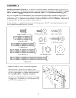
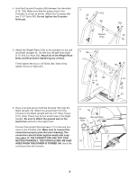
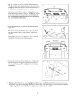
4. Hold the Console Crossbar (88) between the Handrails 4 (112, 103). Make sure that the square hole in the Crossbar is on top as shown. Attach the Crossbar with 112 56 two 2 1/2" Bolts (56). Do not tighten the Crossbar Bolts yet. 88 Square Hole 103 56 5. Attach the Weight Rack (102) to the brackets on the Left and Right Uprights (9, 10) with four Weight Rack Bolts (117) and four Nuts (93). Attach all of the Weight Rack Bolts and Nuts before tightening any of them. Firmly tighten the four 2 1/2" Bolts (56). Next, firmly tighten the two 4" Bolts (87). 5 56 117 56 117 93 102 9 87 10 93 87 6. Have a second person hold the Console (78) near the Right Upright (10). Attach the ground wire from the Console to the Right Upright with the 1/2" Silver Screw (107). Note: There may be two small holes in the Right Upright. Be sure to attach the ground wire to the lower hole and not to the higher hole. Connect the Upright Wire Harness (17) to the wire harness on the Console (78). Make sure to connect the connectors properly (see the inset drawing). The connectors should slide together easily and snap into place. IF THE CONNECTORS ARE NOT CONNECTED PROPERLY, THE CONSOLE MAY BE DAMAGED WHEN THE POWER IS TURNED ON. Insert the connectors into the Console. 6 78 Higher Hole Ground Wire 107 17 17 10 8
-
 1
1 -
2
-
 3
3 -
 4
4 -
 5
5 -
 6
6 -
 7
7 -
 8
8 -
 9
9 -
 10
10 -
 11
11 -
 12
12 -
 13
13 -
14
-
15
-
16
-
17
-
18
-
19
-
20
-
21
-
22
-
23
-
24
-
25
-
26
-
27
-
28
-
29
-
30
-
31
-
32
 |
 |
