Weslo Cadence 150 S Instruction Manual - Page 5
Maintenance And Troubleshooting
 |
View all Weslo Cadence 150 S manuals
Add to My Manuals
Save this manual to your list of manuals |
Page 5 highlights
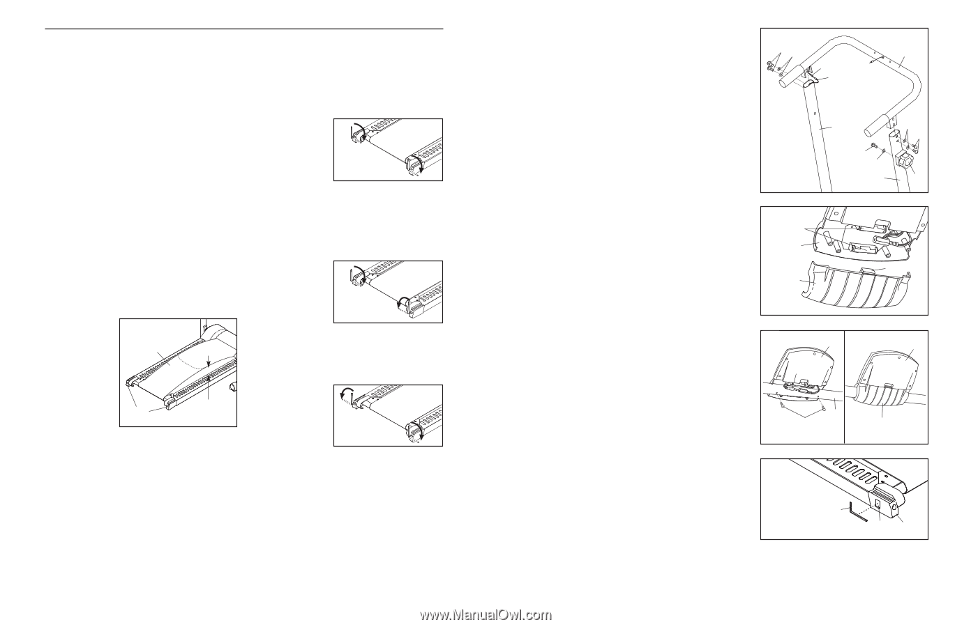
MAINTENANCE AND TROUBLESHOOTING Most problems can be solved by following the simple steps below. If further assistance is needed, please call our Customer Service Department. 1. SYMPTOM: THE CONSOLE DOES NOT FUNCTION PROPERLY 3. SYMPTOM: THE WALKING BELT SLIPS OR IS OFF-CENTRE a. Replace the batteries in the console (see assembly step 5 on page 5). b. Make sure that the reed switch is properly adjusted (see assembly step 3 on page 4). c. Make sure that the handrail wire is plugged fully into the wire on the console (see assembly step 6 on page 5). d. The console, like most electronics, is susceptible to static electricity build-up caused by certain types of clothing or by the operation of the treadmill. If the display is blank or gives incorrect readings, apply an anti-static spray to the handrail. Anti-static spray is available where laundry supplies are sold. 2. SYMPTOM: THE WALKING BELT DOES NOT MOVE SMOOTHLY a. If the walk- ing belt is overtight- Walking ened, per- Belt formance may be reduced and the walking belt may be permanently damaged. Bolts 5-7 cm Using the hex key, turn both rear roller adjustment bolts counter- clockwise 1/4 of a turn. When the tension of the walking belt is correct, you should be able to lift each side of the walking belt 5 to 7 cm (2 to 3 in.). Walk on the treadmill for a few minutes. Repeat until the walking belt is properly tightened. Be careful to keep the walking belt centred. a. If the walking belt slips when walked on, use the hex key to turn both adjustment bolts clockwise, 1/4 of a turn. When the walking belt is correctly tightened, you should be able to lift each side of the walking belt 5 to 7 cm (2 to 3 in.). Walk on the treadmill for a few minutes. Repeat until the walking belt is properly tightened. Be careful to keep the walking belt centred. b. If the walking belt has shifted to the left side, use the hex key to turn the left adjustment bolt clockwise, and the right adjustment bolt counterclockwise, 1/4 of a turn each. Be careful not to overtighten the walking belt. Walk on the treadmill for a few minutes. Repeat until the walking belt is centred. c. If the walking belt has shifted to the right side, use the hex key to turn the left adjustment bolt counterclockwise, and the right adjustment bolt clockwise, 1/4 of a turn each. Be careful not to overtighten the walking belt. Walk on the treadmill for a few minutes. Repeat until the walking belt is centred. 8 4. Hold the Handrail (5) near the Left and Right Uprights (35, 36). Connect the Handrail Wire (2) to the Reed Switch Wire (6). Insert the Wires down into the Left Upright. Attach the Handrail (5) to the Uprights (35, 36) with four M8 x 15mm Bolts (33) and four M8 Washers (34). Be careful not to pinch the Wires (2, 6). See step 1. Tighten the four M8 Nylon Nuts (13). Attach the Resistance Control (44) to the Right Upright (36) with the M5 x 12mm Bolt (46) and the M5 Washer (47). 4 33 34 5 2 6 35 46 47 36 34 33 44 5. The Console (1) requires two "AAA" batteries. Alkaline batteries are recommended. Press the indicated tab on the Battery Cover (27), and remove the Battery Cover. Insert two batteries into the two battery clips; make sure that the negative (-) ends of the batteries are touching the springs in the battery clips. 5 Batteries 1 Tab 27 6. See drawing 6a. Hold the Console (1) near the Handrail 6a (5). Connect the wire on the Console to the Handrail 1 6b 1 Wire (2). Attach the Console to the Handrail with two M4 x 12mm Screws (3). Make sure that the wires are not pinched. 2 See drawing 6b. Press the Battery Cover (27) back onto the Console (1). Make sure that the walking belt is properly tightened (see SYMPTOM 3 on page 8). 5 3 27 7. Remove the paper backing from the Adhesive Clip (30). Press the Adhesive Clip onto the Left Frame Endcap (24) 7 in the indicated location. Press the Hex Key (20) into the Adhesive Clip. 20 30 24 8. Make sure that all parts are properly tightened before you use the treadmill. To protect the floor or carpet, place a mat under the treadmill. 5
-
 1
1 -
 2
2 -
 3
3 -
 4
4 -
 5
5 -
 6
6
 |
 |