Weslo Cadence 620 User Guide - Page 5
Maintenance And Trouble-shooting, Assembly
 |
View all Weslo Cadence 620 manuals
Add to My Manuals
Save this manual to your list of manuals |
Page 5 highlights
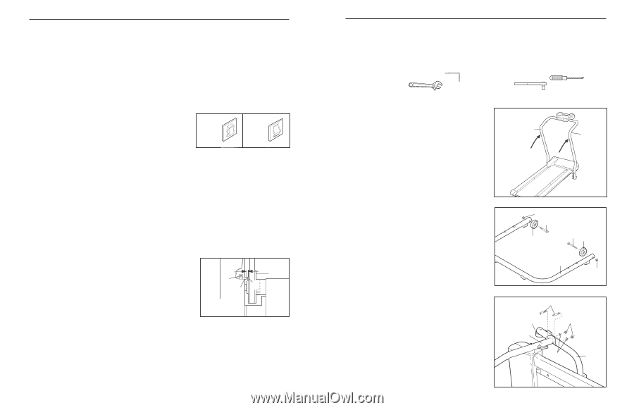
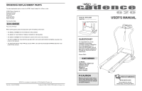
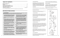
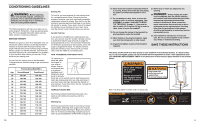
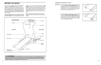
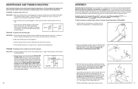
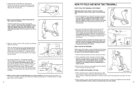
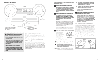
MAINTENANCE AND TROUBLE-SHOOTING Most treadmill problems can be solved by following the steps below. Find the symptom that applies, and follow the steps listed. If further assistance is needed, please call our Customer Service Department. PROBLEM: The power does not turn on SOLUTION: a. Make sure that the power cord is plugged into a properly earthed outlet. (See HOW TO PLUG IN THE POWER CORD on page 7.) If an extension cord is needed, use only a 3-conductor, 14gauge (1mm2) cord that is no longer than 1.5 meters. b. After the power cord has been plugged in, make sure that the key is fully inserted into the console. c. Check the circuit breaker located on the treadmill near the power cord. If the switch protrudes as shown, the circuit breaker has tripped. To reset the circuit breaker, wait for five minutes and then press the switch back in. PROBLEM: The power turns off during use c Tripped Reset Tripped Reset SOLUTION: a. Check the circuit breaker located on the treadmill frame near the power cord (see 1. c. above). If the circuit breaker has tripped, wait for five minutes and then press the switch back in. b. Make sure that the power cord is plugged in. c. Remove the key from the console. Reinsert the key fully into the console. d. If the treadmill still will not run, please call our Customer Service Department. PROBLEM: The displays of the console do not function properly SOLUTION: a. Check the batteries in the console. See assembly step 7 on page 6. Most problems are the result of drained batteries. b. Remove the key from the console and UNPLUG THE POWER CORD. Remove the screws from the hood. Carefully remove the hood. Locate the Reed Switch (46) and the Magnet (49) on the left side of the Pulley (53). Turn the Pulley until the Magnet is aligned with the Reed Switch. Make sure that the gap between the Magnet and the Reed Switch is about 3mm. If necessary, loosen the Screw (26) and move the Reed Switch slightly. Retighten the Screw. Re-attach the hood, and run the treadmill for a few minutes to check for a correct speed reading. 3mm 53 26 49 46 Top View 12 ASSEMBLY Assembly requires two persons. Set the treadmill in a cleared area and remove all packing materials; do not dispose of the packing materials until assembly is completed. Note: The underside of the treadmill walking belt is coated with high-performance lubricant. During shipping, a small amount of lubricant may be transferred to the top of the walking belt or the shipping carton. This does not affect treadmill performance. If there is lubricant on top of the walking belt, simply wipe off the lubricant with a soft cloth and a mild, non-abrasive cleaner. Assembly requires the included allen wrench and your own phillips screwdriver , two adjustable spanners and a 9/16 socket spanner . If further assistance is needed, please call our Customer Service Department at 0345-089009. 1. With the help of a second person, carefully raise the 1 Right and Left Handrails (6, 7) to the position shown. 7 6 2. Using two adjustable wrenches, attach the Wheels (15) to the Base (80) with the two Wheel Bolts (14) and the two 2 Wheel Nuts (84) as shown. Do not overtighten the Wheel Bolts; the Wheels should spin freely. 84 14 15 14 15 80 84 3. With the help of a second person, carefully tip the tread- mill onto its left side. Hold the Base (80) against the Right 3 Handrail (6) and the Left Handrail (not shown). Make sure the Wheels (15) are toward the front of the treadmill as shown. Using a 9/16 socket spanner, attach the Base (80) to the Right Handrail (6) with two Handrail Bolts (12), two Handrail Washers (85), and two Handrail Nuts (17). Do not tighten the Handrail Bolts yet. Attach the Base to the Left Handrail (not shown) with two Handrail Bolts (12), two Handrail Washers (85), and two Handrail Nuts (17). Then, tighten all four Handrail Bolts (12). 12 15 17 6 85 80 Tip the treadmill back to the position shown in step 1. 5
-
 1
1 -
 2
2 -
 3
3 -
 4
4 -
 5
5 -
 6
6 -
 7
7 -
 8
8 -
 9
9 -
 10
10 -
 11
11
 |
 |