Weslo Cadence J3.8 Treadmill User Manual - Page 9
May Be Damaged When The Power Is
 |
View all Weslo Cadence J3.8 Treadmill manuals
Add to My Manuals
Save this manual to your list of manuals |
Page 9 highlights
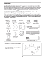
7. Set the Console (91) face-down on a soft sur- 7 face to avoid scratching the Console. Hold the Console Right Handrail (33), which has a large hole in the location shown, near the Console. Next, insert the console wire and tie into the hole Wire 85 Tie Bracket 7 10 in the side of the Right Handrail (33). Using needlenose pliers, pull the console wire out of the hole near the bracket on the Right Handrail. 33 Large Then, set the Right Handrail (33) on the Console Hole (91). Make sure that no wires are pinched. Start a Crossbar Screw (85) with a Crossbar 91 Star Washer (7) into the Right Handrail, and then start two Console Screws (10) into the Right Handrail. Tighten the Crossbar Screw and then the two Console Screws; do not overtighten the Screws. Attach the Left Handrail (not shown) to the Console (91) in the same way. Note: There are no wires on the left side. 8. See the upper inset drawing. If there is a guard 8 on the end of the Console Wire, press the indi- cated tab and remove the guard with needlenose pliers. Discard the guard. With the help of a second person, hold the Console (91) near the Right Upright (54). Connect the Wire Harness (39) to the console wire. See the lower inset drawing. The connectors should slide together easily and snap into place. If they do not, turn one connector and try again. IF THE CONNECTORS ARE NOT CONNECTED PROPERLY, THE CONSOLE MAY BE DAMAGED WHEN THE POWER IS TURNED ON. Insert the connectors and excess wire into the Right Upright (54). Console Wire Tab 91 Guard Console Wire 39 Console Wire 54 39 9
-
 1
1 -
2
-
3
-
 4
4 -
 5
5 -
 6
6 -
 7
7 -
 8
8 -
 9
9 -
 10
10 -
 11
11 -
 12
12 -
 13
13 -
 14
14 -
15
-
16
-
17
-
18
-
19
-
20
-
21
-
22
-
23
-
24
-
25
-
26
-
27
-
28
 |
 |
