Weslo Pursuit 720d Bike English Manual - Page 3
Assembly
 |
View all Weslo Pursuit 720d Bike manuals
Add to My Manuals
Save this manual to your list of manuals |
Page 3 highlights
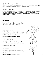
ASSEMBLY Please read all instructions carefully before beginning assembly. Assembly can be completed using the tool provided. Q-4 3 1. Place all bike parts in a clear area on the floor and 2 5 remove the packing materials. Make sure that all parts are included before disposing of the packing materials. 2 2. Attach the Rear Leg (1) to the base of the Frame (5) with two Carriage Bolts (2), Molded Washers (3) and Acorn Nuts (4). 3 3. Thread the Pedal marked "Left" (8) counterclockwise into the left arm of the Crank (7). Thread the Pedal marked "Right" (6) clockwise into the right arm of the Crank. Tighten both pedals firmly. 7 8 3t3 4. Remove the two Screws (32, 33) from the Shock Hood (31) and lift off the Hood. 5. Position the pivot tube of the Handlebar (15) between the holes in the Meter Hood (24), and insert the Pivot Rod (20). Screw the Bolt (21) and Washer (22) into the end of the Pivot Rod, and snap the Plastic Caps (23) into the Meter Hood. 6. Place the end of the Hydraulic Shock (2b) inside of the bracket on the seat tube of the Frame(5)and attach it with the Bolt (29), Washer (30) and Locknut (28). Reattach the Shock Hood with the two Screws. 7. Attach the Seat (10) to the Seat Post (9) with the three Seat Nuts (62). (The nuts must first be removed from the Seat.) Insert the Seat Post into the seat tube of the Frame and tighten the T-Wingnut (14) firmly. The Seat Post must be inserted at least 2 inches. 8. Remove the screw from the Resistance Control Knob (18), clip the Knob onto the right side of the Handlebar, then attach the Knob by replacina the screw. Moisten the ends of the Handlebar (15) with soapy water and push the Handgrips (16) on. Insert the Handgrip Caps (17) into the ends of the Handlebar. 9. Make sure that all parts are tightened securely before 4 using the bike. 4 31 3!2 ti 15 24 5 2122'')8r 4 1 2a, 23 20 '2 6 29 - 28 5. 9 7 2 /10 • 14 keit 9 18 8 15 17 16
-
 1
1 -
 2
2 -
 3
3 -
 4
4 -
 5
5 -
 6
6 -
 7
7 -
 8
8 -
 9
9 -
10
 |
 |
