Weslo Pursuit E 25 Bike English Manual - Page 5
Seat Post.
 |
View all Weslo Pursuit E 25 Bike manuals
Add to My Manuals
Save this manual to your list of manuals |
Page 5 highlights
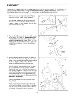
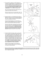
4. The Console (7) requires one "AAA" battery (not 4 included); an alkaline battery is recommended. Refer to the inset drawing. Remove the battery door from the back of the Console and insert the battery into the Console. Make sure that the battery is orient- ed as shown by the diagram inside the battery compartment. Then, reattach the battery door. Next, plug the Reed Switch Wire (28) fully into the socket on the back of the Console (7). Slide the Console onto the console plate. Note: The Console is held by friction; it does not snap into place. 5. Attach the Seat (11) to the Seat Post (10) with four 5 M8 Nylon Locknuts (9) and four M8 Spring Washers (8). Note: The Nylon Locknuts and Spring Washers may be pre-attached to the Seat. Press the Frame Bushing (4) into the Frame (1). (Note: The Frame Bushing may be pre-assembled.) Next, insert the Seat Post (10) into the Frame. Align one of the holes in the Seat Post (10) with the hole in the Frame (1). Insert the Seat Pin (31) into the Frame and the Seat Post. Make sure that the Seat Pin is inserted into one of the holes in the Seat Post; do not insert the Seat Pin under the Seat Post. Tighten the Seat Pin into the Frame. 6. Identify the Right Pedal (22), which is marked with 6 an "R." Remove only the Right Pedal Nut (47) and the Pedal Bushing (46) from the Pedal. Next, insert the shaft of the Pedal into the right Pedal Arm (49). Slide the Pedal Bushing back onto the Pedal, and position the Pedal Bushing so that it slides into the Pedal Arm. Tighten the shaft of the Pedal clockwise into the right arm of the Crank (20) as firmly as pos- sible. Tighten the Pedal Nut clockwise onto the Pedal. Make sure that the Pedal and the Pedal Nut are tightened as firmly as possible. Repeat this step to attach the Left Pedal (not shown), turning the Pedal and the Left Pedal Nut (not shown) counterclockwise. Console Plate 7 28 Battery Battery Door 11 8 8 9 9 10 4 31 Hole 1 47 46 44 22 49 20 7. Make sure that all parts are properly tightened before you use the exercise cycle. Note: Some hardware may be left over after assembly is completed. Place a mat under the exercise cycle to protect the floor or carpet from damage. 5
-
 1
1 -
 2
2 -
 3
3 -
 4
4 -
 5
5 -
 6
6 -
 7
7 -
 8
8 -
 9
9 -
 10
10 -
 11
11 -
12
 |
 |
